Do you have a question about the Dantherm 4000 and is the answer not in the manual?
This service manual covers the following main topics.
This service manual is designed for technicians who install and maintain the DC Air Conditioner.
Copying of this service manual, or part of it, is forbidden without prior written permission.
Dantherm reserves the right to make changes and improvements to the product and the service manual.
This section describes the overall product and its functionality.
This manual covers a series of air conditioners, detailing available models.
This table shows the accessories available from the supplier.
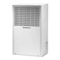
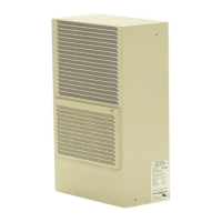
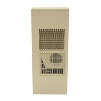
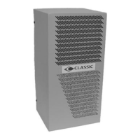
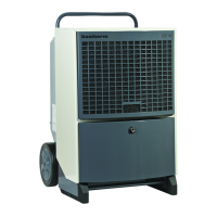
This illustrates the unit's outdoor view and its parts.
This air conditioner includes a condensate drain that routes water away from the unit.
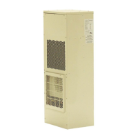
This illustrates the unit's indoor view and its parts.
This section describes the airflow of the Air conditioner and how it operates.
Describes the optional pre-filter for the external air inlet to reduce intrusion of debris.
This section describes key features of the electronic control and how it operates.
Never perform installation, maintenance or service without disconnecting the AC power supply.
Details basic parameters and extended settings via the onboard control panel and SD card.
Explains how the controller manages fans, heater, and compressor based on temperature.
This illustrates the operation panel seen from inside the unit.
This illustration shows the external connections to the controller.
Output that toggles state on operation errors. Default open/close configurable.
Output that toggles state if highest temperature limit is exceeded. Default open/close configurable.
Input that can control and overrule operation parameters. Active when low.
Input that can control and overrule operation parameters. Active when low.
Temperature sensor for placement inside the enclosure in a hotspot zone.
The unit can operate on the built-in operation panel, with parameters set via TTL or SD card.
Explains the functionality of the control panel keys (Up, Down, Enter).
Describes menu structure and navigation for reading or changing parameters.
This table shows the meaning of each error code the unit can generate.
This table shows the steps included in the unit's self-test program.
This unit is designed for outdoor mounting, flush to the wall.
Guidance on placing the unit for optimal airflow inside the enclosure.
Dimensions for marking wall cutouts and holes.
Instructions for unpacking, preparing sheet metal parts, and installing the gasket.
Steps for lifting the unit into cutouts, securing with bolts, and sealing junctions.
Covers national wiring regulations, power supply protection, and cable securing for safe installation.
Details routing, securing, and connecting power supply cords and accessories.
Explains the importance, schedule, and benefits of preventive maintenance.
Details the recommended preventive maintenance plan for cleaning the unit.
Steps to inspect the unit prior to re-assembly and putting it back into service.
Instructions for testing the cooling circuit if a relevant problem has arisen.
Method for testing the compressor's safety switch (Klixon).
Visual guide to spare parts for the condenser section of the unit.
Visual guide to spare parts for the evaporator section of the unit.
General description of unit design and features.
Table detailing technical specifications for the 4000 and 6000 BTU models.
Diagram showing complete controller connections, internal as well as external.
Illustration of the unit's detailed electrical schematics.
This illustration shows the cooling circuit schematic.
Statement of compliance with directives like UL and CSA standards.
Guidelines for environmentally responsible recycling of the unit.
| Refrigerant | R410A |
|---|---|
| Energy Efficiency Class (Cooling) | A |
| Power Supply | 230V/50Hz |
| Weight (Indoor Unit) | 12 kg |
| Weight (Outdoor Unit) | 35 kg |
| Dimensions (Indoor Unit) | 700x250x190 mm |
| Dimensions (Outdoor Unit) | 800x290x540 mm |