Chapter 1
4
Getting Started Procedure
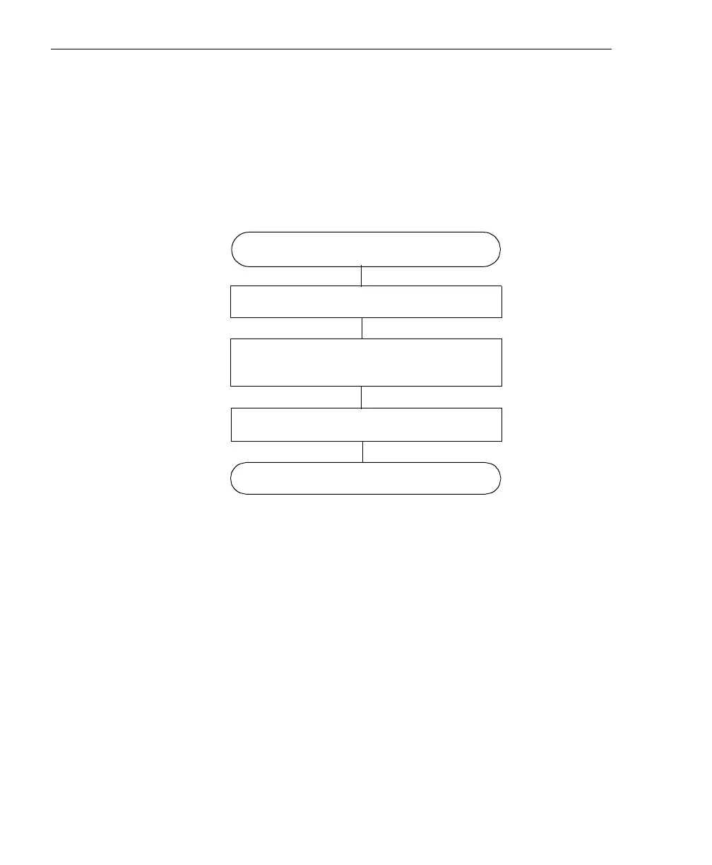
The flow diagram shown in Figure 1 illustrates the steps needed to
get started using a DT300 Series board. This diagram is repeated in
each chapter; the shaded area in the diagram shows you where you
are in the getting started procedure.
Figure 1: Getting Started Flow Diagram
Install the Board and Load the Device
Driver (see Chapter 3 starting on page 13)
Wire Signals
(see Chapter 5 starting on page 35)
Verify the Operation of the Board
(see Chapter 6 starting on page 65)
Attach and Configure the Screw Terminal
Panel and Signal Conditioning Backplane
(see Chapter 4 starting on page 23)
Prepare to Use a Board
(see Chapter 2 starting on page 5)
 Loading...