Attaching and Configuring a Screw Terminal Panel/ Backplane
31
4
4
4
4
4
4
4
4
4
Using a 5B01 or 5B08 Signal Conditioning
Backplane
This section describes how to attach a 5B01 or 5B08 signal
conditioning backplane to an STP300 screw terminal panel and how
to configure the backplane for use with a DT300 Series board.
Attaching a 5B01 or 5B08 Backplane
If you want to condition your analog signals, you can attach a 5B01 or
5B08 signal conditioning backplane to the STP300 using the AC1315
cable. The 5B01 and 5B08 backplanes, 5B Series signal conditioning
modules, and the AC1315 cable are offered by Data Translation as
accessories to the DT300 Series boards.
To attach a 5B01 or 5B08 backplane to the STP300 screw terminal
panel, perform the following steps:
1. Plug one end of the AC1315 cable into the J2 connector of the
STP300 screw terminal panel, as shown in Figure 6.
2. Plug the other end of the AC1315 cable into the 26-pin connector
on the 5B01 or 5B08 backplane.
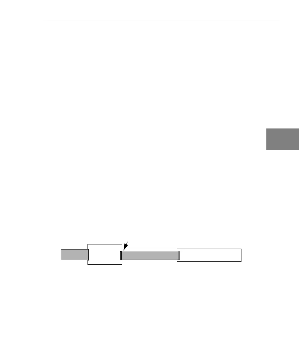
Figure 6: Connecting the 5B01 or 5B08 Backplane to the STP300
STP300
AC1315
Cable
J2 Connector
5B01 or 5B08
To DT300 Series
board
 Loading...