Wiring Signals
61
5
5
5
5
5
5
5
5
5
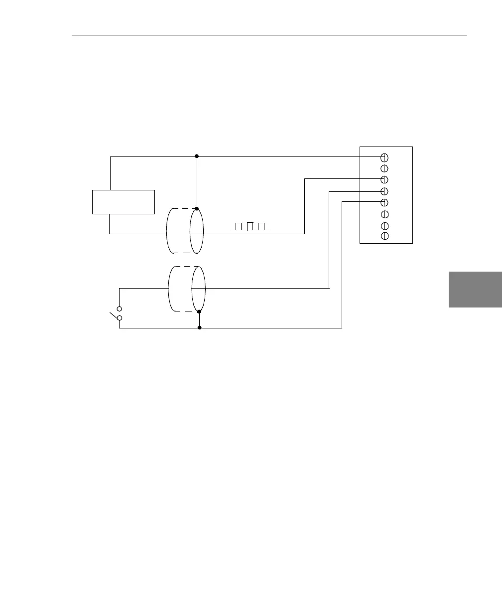
Connecting Pulse Output Signals
Figure 20 shows one example of connecting pulse output signals to
the STP300 screw terminal panel using user counter 0.
Figure 20: Connecting Pulse Output Signals
(Shown for Counter Output 0 and Gate 0)
Figure 21 shows an example of how to externally cascade two
counters to perform a rate generation operation using user counters 0
and 1. Note that you can also cascade counters internally using
software; if you internally cascade the counters, you do not need to
make the external cascading connections. In this example, counter 1
gate is logic high.
STP300 Panel
TB27
Heater
Controller
Digital Ground
TB29
TB28
Digital Ground
Gate 0
External
Gating
Switch
TB25
User Counter Output 0
 Loading...