DATAKOM DKG-705 User’s Manual
705_USER.doc - 47 -
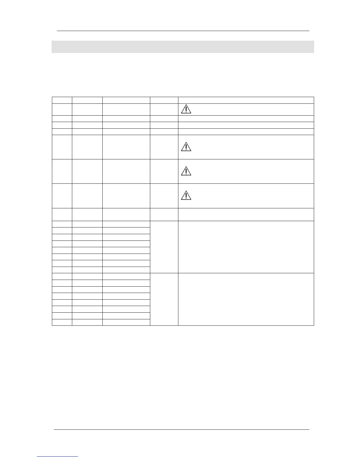
Program Group: 8
This group defines the functions of relay outputs. The DKG-705 base unit has 7 relay outputs. The
relays may be extended up to 23 using Relay Extension Modules.
The function of a given relay output may be selected from a list of 112 entries. Here are the usual
functions of the internal relays.
Group
Description / Usual Function
8 800
Relay 0 function
-
This relay output is not provided
8 801
Relay 1 function
36 Auxiliary relay output, mostly used as Preheat output.
8 802
Relay 2 function
33
Start relay output.
8 803
Relay 3 function
37 Auxiliary relay output, mostly used as Alarm output.
8 804
Relay 4 function
1
Generator contactor relay output.
The common terminal of the internal relay is
connected to the generator phase U.
8 805
Relay 5 function
10
Mains contactor relay output.
The common terminal of the internal relay is
connected to the mains phase R.
8 806
Relay 6 function
32
Fuel relay output.
This relay output feeds also the charge
alternator excitation circuit.
8 807
Relay 7 function
35 Auxiliary relay output, mostly used as Activate to
Stop output.
8 808
Relay 8 function
8 809
Relay 9 function
8 810
Relay 10 function
8 811
Relay 11 function
8 812
Relay 12 function
8 813
Relay 13 function
8 814
Relay 14 function
8 815
Relay 15 function
- These relays are found on the first Relay Extension
Module.
8 816
Relay 16 function
8 817
Relay 17 function
8 818
Relay 18 function
8 819
Relay 19 function
8 820
Relay 20 function
8 821
Relay 21 function
8 822
Relay 22 function
8 823
Relay 23 function
- These relays are found on the second Relay
Extension Module.
 Loading...