DX8200 CONTROLLER
QUICK GUIDE
5
Accessories:
Name Description Part Number
CAB-8101 Cable master/slave 1 m 93A051020
CAB-8102 Cable master/slave 2 m 93A051030
CAB-8105 Cable master/slave 5 m 93A051040
CAB-8305 Cable power + termination 5 m 93A051268
INT-60 20 mA C.L. interface board 93A151021
PWR-120 Power unit 110/230 V AC - 24 V DC 93ACC1530
BTK-8000 Terminator kit (5 pcs) 93ACC1090
Electrical Connections:
The DX8200 is equipped with the following connectors for electrical connections:
•
••
•
Host Interface Connector (serial interface and I/O signals)
(male, 25 pins)
•
••
•
Ethernet Connector
(RJ45)
•
••
•
Lonworks Network Connector
(female, 17 pins)
•
••
•
RS232 Debug Connector – for Service only
(female, 9 pins)
•
••
•
Reserved Connector
(female, 9 pins)
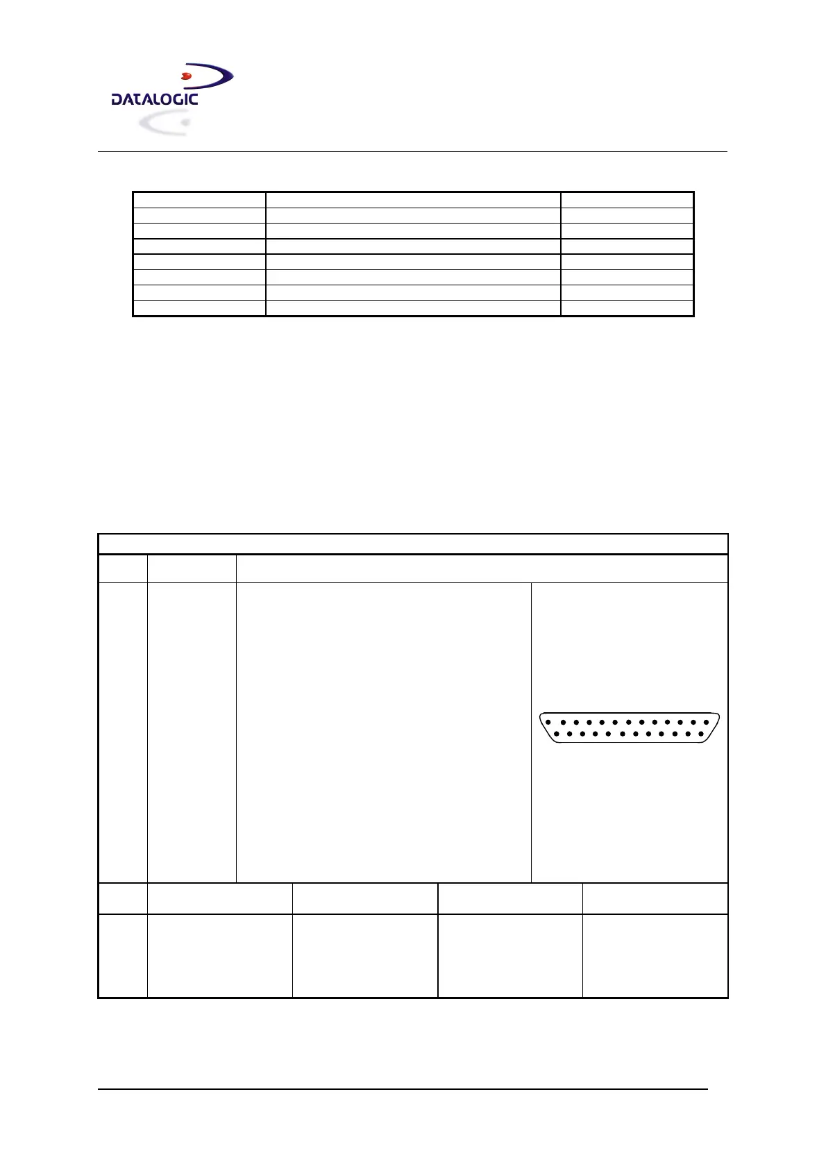
Host Interface Connector
The 25-pin male D-sub connector provides connection to Host interface (Main and Aux), and input/output signals.
Host Interface Connector Pinout
Pin Name Function
1 Shield Internally connected by capacitor to chassis
20 RXAUX Receive data of auxiliary RS232 (referred to GND)
21 TXAUX Transmit data of auxiliary RS232 (referred to GND)
8 OUT 1+ Configurable digital output 1 – positive pin
22 OUT 1- Configurable digital output 1 – negative pin
11 OUT 2+ Configurable digital output 2 – positive pin
12 OUT 2- Configurable digital output 2 – negative pin
16 OUT 3A Configurable digital output 3 – polarity insensitive
17 OUT 3B Configurable digital output 3 – polarity insensitive
18 EXT_TRIG A External trigger (polarity insensitive)
19 EXT_TRIG B External trigger (polarity insensitive)
6 ENC A Encoder input signal (polarity insensitive)
10 ENC B Encoder input signal (polarity insensitive)
14 IN3A Input signal 3
15 IN4A Input signal 4
24 IN_REF Common reference of IN3 and IN4
9, 13 VS VDC I/O supply voltage – positive pin
23, 25 GND VDC I/O supply voltage – negative pin
14
1
25
13
25-pin male D-sub
Pin RS232 RS485 Full-Duplex RS485 Half-Duplex
20 mA C.L.
(INT-60 Only)
2 TX TX485+ RTX485+ CLOUT+
3 RX RX485+ CLIN+
4 RTS TX485- RTX485- CLOUT-
5 CTS RX485- CLIN-
7 GND_ISO GND_ISO GND_ISO GND*
* For 20 mA C.L. connections, GND is the same of the scanner power supply.
 Loading...