Using the BC40xx™ Radio Base
Quick Reference Guide 19
Using the BC40xx™ Radio Base
Base LEDs
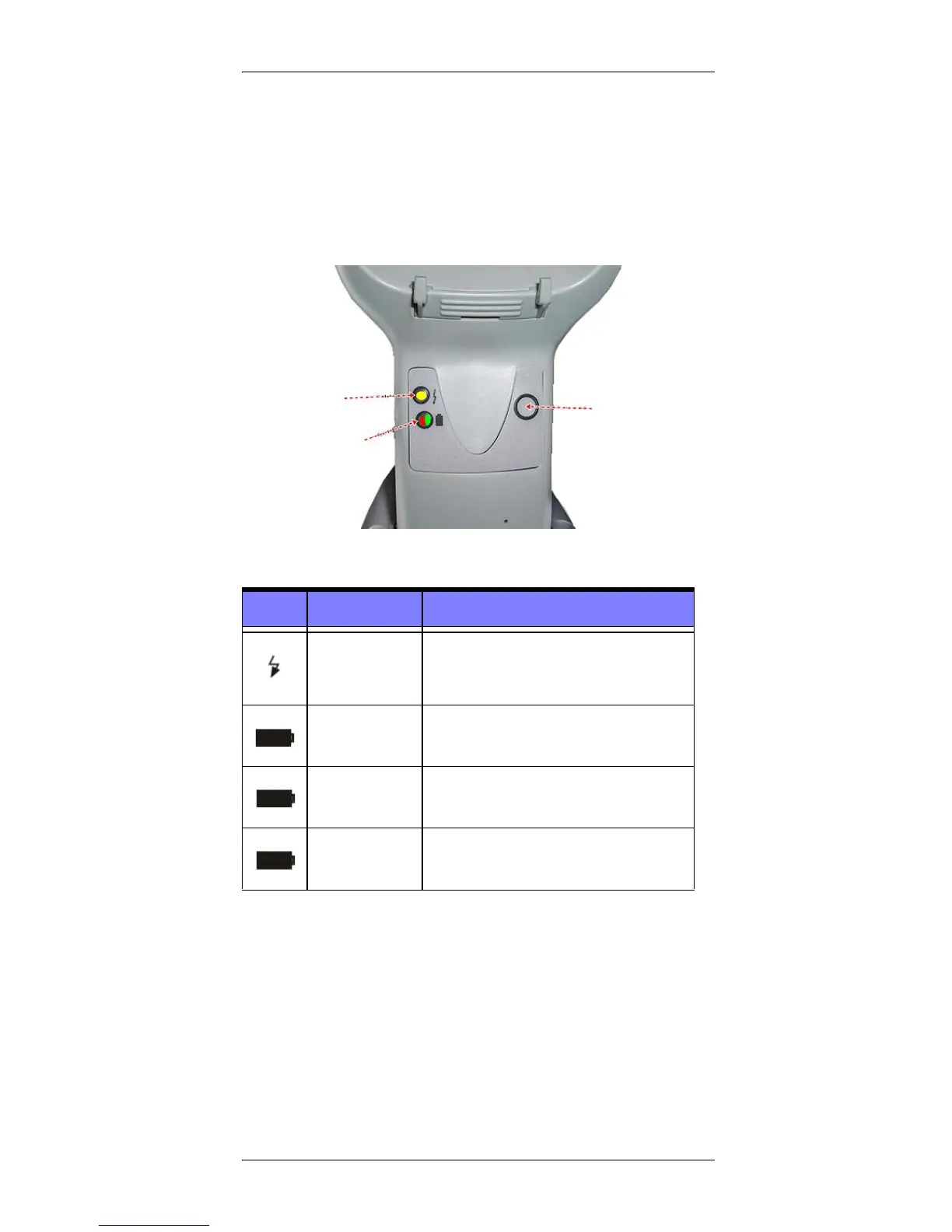
LEDs on the Gryphon I Base provide information about the
Base’s status, as shown in Figure 9.
Figure 9. Gryphon I Base LEDs
The following table describes the significance of each LED:
A button is available to force device connection via the Datalogic
Aladdin Software tool, and for paging the scanner when bidirec-
tional connection is activated. Refer to the Gryphon I Product
Reference Guide (PRG) for a more detailed explanation.
LED STATUS
Power on / Data
Yellow On = Base is powered
Yellow Blinking = Base receives data and
commands from the Host or the Reader.
Charging Red On = the Battery is in progress.
Charge completed Green On = the Battery is completely charged.
Charging +
Charge completed
Red and Green Blinking together = the Reader
is not correctly placed onto the Base.

 Loading...