MATRIX-2000™ QUICK GUIDE
5
9-pin female D-sub connector pinout
Pin Name Function
2 TXAUX
Transmitted data of auxiliary RS232
3 RXAUX
Received data of auxiliary RS232
5 GND
Reference GND of auxiliary RS232
5
1
9
6
1,4,6,7,8,9 N.C.
Not connected
RJ45 modular jack pinout
Pin Name Function
1 TX + Transmitted data (+)
2 TX - Transmitted data (-)
3 RX + Received data (+)
6 RX - Received data (-)
4,5,7,8 N.C. Not connected
1
8
For further details refer to the Ethernet Folder in the VisiSet™ Help-On-Line and to the "MatrixEthernet.pdf"
document provided as supplementary documentation.
User Interface:
RS232 PC-side connections
1
5
9 6
9-pin male connector
13
25 14
1
25-pin male connector
Pin Name Pin Name
2 RX 3 RX
3 TX 2 TX
5 GND 7 GND
7 RTS 4 RTS
8 CTS 5 CTS
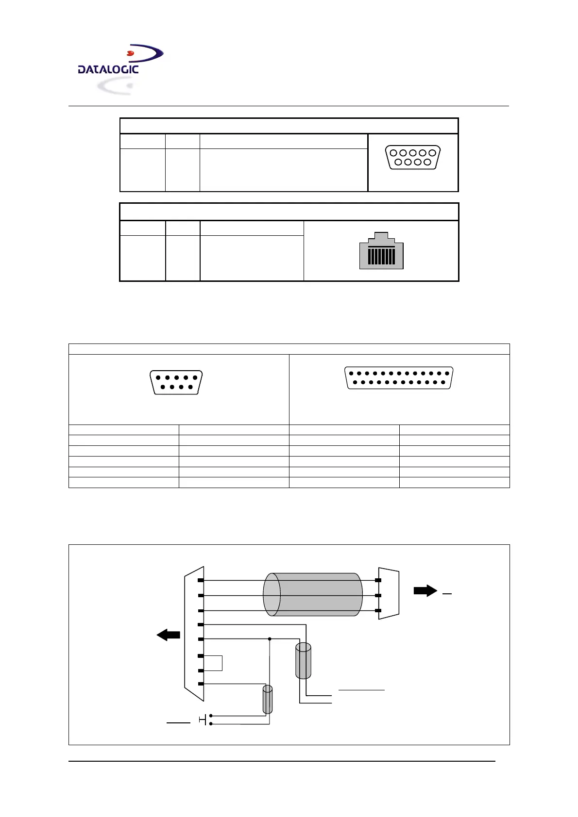
How to Build a Simple Interface Test Cable:
The following wiring diagram shows a simple test cable including power, external (push-button) trigger and PC
RS232 COM port connections.
25-pin D-sub female
23
20
GND
RXAUX
TXAUX
21
MATRIX
25
13
GND
VS
9-pin D-sub female
GND
TX
RX
PC
2
3
5
18
9
EXT TRIG+
VS
Power Supply
VS (10 – 30 VDC)
Power GND
Trigger
EXT TRIG-
19
Test Cable for Matrix-2000™