EasyManua.ls Logo

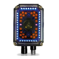
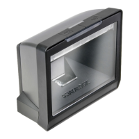
Datalogic Matrix-2000

Datalogic Matrix-2000
11 pages
To Next Page IconTo Next Page
Loading...
Matrix-2000™
Quick Reference Guide
Figure A
Reading Window
Positioning LED
Calibration LED
Communication LED
Keypad button
1
2
4
5
3
6
9
8
7
Main/Auxiliary Interface
A
uxiliary Interface
Good Read LED
Ethernet Interface (for 21XX
models only)
10
External Trigger LED
Power On LED
11
NOTE
For further details on product installation, see the complete Installation Manual available on
the CD included with this product.
Compliance:
- This product is intended to be installed by Qualified Personnel only.
- This product is intended to be connected to a UL Listed
Computer which supplies power directly to the reader or a
UL Listed Direct Plug-in Power Unit marked LPS or
“Class 2”, rated 10 to 30 V, minimum 1 A.
- In order to meet the EMC requirements:
connect reader chassis to the plant earth ground by
means of a flat copper braid shorter than 100 mm;
connect the main interface cable shield to pin 1 of the
reader 25-pin connector;
use two clip-on ferrite sleeves (type Stewart 28A2029-
0A0) on the main interface cable near the reader 25-
pin connector;
connect the Ethernet interface cable shield to the
reader chassis (for Matrix-21XX only)
TO EN 60825-1:2001
Model Description:
MATRIX - 2XXX-X
Optics
1 = Ultra High Density (UHD)
2 = High Density (HD)
3 = Standard Density (SD)
4 = Low Density (LD)
5 = Medium Range (MR)
6 = Long Range (LR)
Image Sensor
1 = VGA CCD
5 = SXGA CMOS
Device Connectivit
y
0 = RS232/RS485 + RS232
1 = RS232/RS485 + RS232+ Ethernet
Other Options
R = 90° Reading Window
6
7
8
2
3
4
5
9
10
11
1
Question and Answer IconNeed help?

Do you have a question about the Datalogic Matrix-2000 and is the answer not in the manual?

Datalogic Matrix-2000 Specifications

General IconGeneral
Type2D Imager
Resolution4 mils (depending on bar code density)
ProtectionIP65
InterfaceUSB, RS-232, Ethernet
Decode Capability1D and 2D barcodes
Scan Rate60 fps
Operating Temperature32°F to 122°F (0°C to 50°C)
Storage Temperature-40°C to 70°C
Humidity5% to 95% non-condensing
Power Supply5V DC
Light SourceRed LED (630-670 nm)

Summary

Product Compliance and Model Overview

EMC Compliance Requirements

Essential requirements for meeting electromagnetic compatibility standards.

Model Description: Connectivity and Optics

Details device connectivity, optics, and image sensor options.

Additional Model Configuration Options

Lists other available configuration options for the reader.

Electrical and Optical Specifications

Power, Communication Interfaces, and Lighting

Covers power supply, communication speeds, and lighting system details.

User Interface and Software Features

Details LED indicators, keypad, and supported code symbologies.

Operating Modes and Mechanical Data

Operating and Configuration Modes

Specifies available operating and configuration modes.

Mechanical Dimensions and Material

Provides physical dimensions, weight, and material of the device.

Environmental and Reading Performance

Environmental Operating Conditions

Details operating temperature, humidity, vibration, and shock resistance.

Reading Features: Frame Rate and Models

Specifies frame rate, pitch, tilt, and detailed reading specs for each model.

Accessories and Electrical Connections

Available Accessories List

Lists available accessories with order numbers and descriptions.

25-Pin D-Sub Connector Pinout and Main Interface

Details the 25-pin connector pinout and main interface assignments.

Auxiliary, Ethernet, and PC Interfaces

9-Pin D-Sub and RJ45 Ethernet Pinouts

Details pinouts for auxiliary 9-pin D-sub and RJ45 Ethernet connectors.

PC RS232 Connections and Test Cable Guide

Shows PC RS232 connections and provides a test cable wiring diagram.

C-BOX 100 Terminal Block Pinout Details

Power, Input, and Output Pin Assignments

Details power, input, and output pin assignments on the C-BOX 100.

Auxiliary and Main Interface Pin Assignments

Lists pin assignments for auxiliary and main interfaces on the C-BOX 100.

Input and Output Connection Schematics

Input Signal Configurations and Features

Explains input connection types (PNP, NPN) and their electrical features.

Output Signal Configurations and Features

Details output connection types (open collector) and their electrical features.

Mechanical Installation and Dimensions

Device Overall Dimensions

Shows physical dimensions for standard and 90° models.

Mounting Bracket Dimensions

Provides dimensions related to mounting brackets.

Connectivity Diagrams and Configurations

Point-to-Point, Multiplexer, and RS232 Setups

Illustrates point-to-point, multiplexer, and RS232 Master/Slave connectivity.

Ethernet Network and Pass Through Configurations

Depicts Ethernet network and pass-through connectivity setups.

Autolearning Configuration Procedure

Autolearning Steps and Best Practices

Step-by-step guide and tips for optimal autolearning configuration.

Autolearning Notes and Cancellation

Important notes, saving modes, and procedures for cancelling autolearning.

Declaration of Conformity and Standards

EU Directives and Product Compliance Standards

Lists relevant EU directives and product compliance standards.

Related product manuals