EasyManua.ls Logo

Datalogic Matrix 300N User Manual

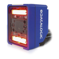
Datalogic Matrix 300N
248 pages
To Next Page IconTo Next Page
Page #1 background imageLoading...
Page #1 background image
Matrix 300N™
Product Reference Guide
Image Based Reader

Table of Contents

Other manuals for Datalogic Matrix 300N

Questions and Answers:

Datalogic Matrix 300N Specifications

General IconGeneral
TypeBarcode module bar barcode readers
Sensor typeCMOS
Scanner type1D/2D
Yaw reading angle0 - 24 °
Optical sensor resolution1024 pixels
Linear (1D) barcodes supported-
2D (matrix & stacked) barcodes supportedAztec Code, Data Matrix, MaxiCode, Micro QR Code, QR Code
Input voltage10 - 30 V
Power consumption (typical)5 W
Connectivity technologyWired
CertificationAIM DPM, ISO/IEC 15415, ISO/IEC 15416, ISO/IEC 16022, ISO/IEC 18004, AS9132A
Product colorBlue, Metallic
Housing materialAluminium, Plastic
International Protection (IP) codeIP67
Storage temperature (T-T)-20 - 70 °C
Operating temperature (T-T)0 - 50 °C
Weight and Dimensions IconWeight and Dimensions
Depth54 mm
Width75 mm
Height62 mm
Weight238 g

Summary

Chapter 1 Rapid Configuration

Step 1 - Connect the System

Instructions for connecting the Matrix 300N reader to a system in a standalone configuration.

Step 2 - Mount and Position the Reader

Guidance on physically mounting and orienting the reader for optimal reading performance.

Step 3 - Aim and Autofocus the Reader

Procedure for using the built-in aiming system and autofocus feature for reader positioning.

Step 4 - X-PRESS Configuration

Configuration steps using the X-PRESS interface for optimal code reading relative to your application.

Step 5 - Installing DL.CODE Configuration Program

Steps to download, install, and run the DL.CODE configuration software on a PC.

Step 6 - Device Configuration

Detailed configuration of reader settings, including automatic and advanced setup options.

Step 7 - Test Mode

How to use test mode to evaluate reader reading performance with suitable codes.

Advanced Reader Configuration

Overview of advanced product configuration options, referring to DL.CODE User's Guide.

Host Mode Programming

Partial configuration of the reader from a host computer using host mode programming.

Chapter 2 Introduction

Product Description

Overview of the Matrix 300N reader, its design, features, and industrial applications.

Standard Application Program

Details on the factory-loaded program controlling reading, data formatting, and interfacing.

Programmability

Information on custom application programs and reader programmability.

Excellent Performance

Highlights of the reader's key performance features, including sensor and decoding capabilities.

Ease of Setup and Use

Features that enhance the ease of setup and use, including X-PRESS interface and DL.CODE.

Flexible Solution

Description of the reader's flexibility in terms of focus, illumination, and connectivity.

Industrial Connectivity

Overview of the reader's connectivity options, including Ethernet and serial interfaces.

Indicator and Keypad Button

Indicators

Explanation of the reader's LED indicators and their meaning during normal operation.

ID-NET

ID-NET Synchronized Network

Configuration for synchronized ID-NET networks enabling multi-point or multi-sided reading.

ID-NET Multidata Network (Pass-Through)

Setup for ID-NET networks using pass-through for multidata collection from multiple slaves.

X-PRESS Human Machine Interface

X-PRESS Functions

Description of functions accessible via the X-PRESS interface and push button for installation and maintenance.

Model Description

Diagnostic Indication

How LED indicators signal error conditions and diagnostic messages.

Lighting System Notes

Table showing Matrix 300N lens/illuminator combinations and their types.

Accessories

List of accessories that can be used with the Matrix 300N reader.

Application Examples

Examples of Matrix 300N applications, including document handling and code reading.

Chapter 3 Installation

Package Contents

List of items included in the Matrix 300N reader package upon opening.

Mechanical Dimensions

Detailed physical dimensions and mounting hole specifications of the reader.

Mounting And Positioning Matrix 300N

Guidance on using mounting brackets for reader positioning and orientation.

Chapter 4 CBX Electrical Connections

Power Supply

Details on supplying power to standard and PoE models via the CBX connection box.

Main Serial Interface

Information on connecting and configuring the main RS232/RS422 serial interface.

ID-NET Interface

Configuration and connection details for the ID-NET high-speed interface.

Inputs

Description of optocoupled polarity insensitive inputs for external triggers and generic inputs.

Outputs

Details on the three general-purpose configurable digital outputs available on the M12 connector.

Chapter 5 Typical Layouts

Ethernet Connection

Describes point-to-point and network Ethernet connection layouts for the reader.

Serial Connection

Layout for transmitting data to a host via the main serial interface.

Fieldbus Connection

How to connect the reader as a slave node on a Fieldbus network.

Pass-Through

Configuration for devices to collect and pass data through other devices.

ID-NET Multidata Network (Pass-Through)

Setup for ID-NET networks using pass-through for multidata collection.

ID-NET Synchronized Network

Configuration for synchronized ID-NET networks with multiple readers.

Chapter 6 Reading Features

FOV Calculation

Formula and data for calculating the Field of View (FOV) for application planning.

Global FOV Diagrams

Diagrams showing maximum obtainable Field of View for various models and code types.

Reading Diagrams

Reference diagrams for typical performance under various conditions and settings.

Maximum Line Speed and Exposure Time Calculations

Chapter 7 Software Configuration

DL.CODE System Requirements

Minimum hardware and software requirements for installing and running DL.CODE.

Reader Configuration

Overview of reader configuration steps, including Auto-Calibration and Manual Calibration.

Multi Image Acquisition Settings

Defining multiple parameter groups to handle varying application conditions.

Image Cropping

Using image cropping to reduce processing area and improve performance.

Image Filter

Applying image filters like Erode, Dilate, Close, Open, etc., to enhance code readability.

Pass-Through Configurations

Setting up pass-through configurations for multi-device data collection.

Internal Network Configurations

Configuring master/slave networks using DL.CODE for data collection.

Verify Master/Slave Synchronized Configuration

How to verify the performance of synchronized master/slave networks.

Backup and Restore Through DL.CODE

Procedures for backing up and restoring reader configurations using DL.CODE.

Replacement

Steps for replacing a device and restoring its configuration to a new unit.

Restore Defaults

Restoring default startup or environment parameters for the reader.

Diagnostic Alarms

How to view and interpret diagnostic alarms and status information.

Statistics

Viewing reading performance statistics and enabled counters.

BM150 Display Module Configuration and Messages

Configuring and using the BM150 display module for reader interaction.

Chapter 8 Illuminators

Standard Illuminators (Wide, Medium, and Narrow Angle)

Overview of standard illuminator types and their combinations.

Diffused Red Illuminator

Details on the diffused red illuminator, its sectors, and applications.

MLT-DPM Illuminator

Information on MLT-DPM illuminators for direct part marking applications.

Polarized Illuminators

Using polarized illuminators to reduce reflections on surfaces.

Direct Part Marking Applications

Guidance on using illuminators for direct part marking challenges.

Matrix 300N Recommended Illumination for DPM

Recommendations for suitable lighting systems for DPM applications.

Lighting System Working Distances

Working distance specifications for various lighting systems and reader models.

Chapter 9 Maintenance

Cleaning

Instructions for cleaning the reader's lens cover to ensure optimal performance.

Chapter 10 Troubleshooting

General Guidelines

General advice for troubleshooting issues, including wiring and parameter checks.

Chapter 11 Technical Features

Electrical Features

Specifications for power, consumption, and communication interfaces.

Optical Features

Details on image sensor, format, frame rate, lenses, and aiming system.

Environmental Features

Operating and storage conditions, humidity, and resistance specifications.

Physical Features

Dimensions, weight, and material specifications of the reader.

Software Features

Supported code symbologies, operating modes, and configuration methods.

Code Quality Metrics

Standards for evaluating code quality.

User Interface

LED Indicators

Explanation of the status and function of the reader's LED indicators.

Keypad Button

How the keypad button is used for configuration and navigation.

Beeper

Information on the reader's configurable beeper functionality.

Appendix A Alternative Connections

Power, Com and I/O Connector

Pinout details for the M12 17-pin connector for power, serial, and I/O signals.

On-Board Ethernet Connector

Pinout and specifications for the M12 D-Coded Ethernet connector.

Power over Ethernet (PoE) Models

Connection requirements and supported alternatives for PoE models.

ID-NET Network Termination

Instructions for properly terminating the ID-NET network.

Inputs

Details on the optocoupled inputs available on the M12 17-pin connector.

Outputs

Pinout and electrical features of the three non-isolated outputs on the M12 17-pin connector.

User Interface - Serial Host

How To Build A Simple Interface Test Cable

Wiring diagram for creating a test cable for serial host communication.

Glossary

AIM

Definition of AIM (Association for Automatic Identification and Mobility).

Barcodes (1D Codes)

Definition of 1D barcodes and their general format.

Bright Field Illumination

Explanation of bright field illumination techniques for reflective surfaces.

Decode

The process of recognizing and analyzing barcode symbologies.

Depth of Field

The range of distances over which an object appears in focus.

Direct Part Mark (DPM)

Definition of symbols marked directly on parts using specialized techniques.

Exposure Time

The duration the image sensor is exposed to light during image acquisition.

IP Address

Definition of an IP address for network identification and data routing.

Matrix Symbologies (2D Codes)

Description of 2D matrix symbols with regular polygon cells.

Symbol Verification

The process of checking if a code meets specific requirements.

Related product manuals