Installation
54
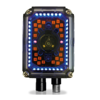
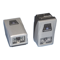
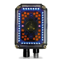
Matrix 300N
Mechanical Dimensions
Matrix 300N can be installed to operate in different positions. The two screw
holes (M4 x 5) on the body of the reader are for mechanical fixture (Figure 24).
The diagrams below give the o
verall dimensions of the reader and may be used
for its installation.
Refer to page 57 for various mounting solutions
and correct positioning, and
Chapter 6 for FOV vs. Reading Distance considerations.
mm
[inch]
optical axis
Connector block
rotates to 90° position
Figure 24 - Overall Dimensions Matrix 300N 1.3 MP and 2 MP DPM with Connector at 0°
Figure 25 - Overall Dimensions Matrix 300N 1.3 MP and 2 MP DPM with Connector at 90°
 Loading...
