Typical Layouts
90
Matrix 300N
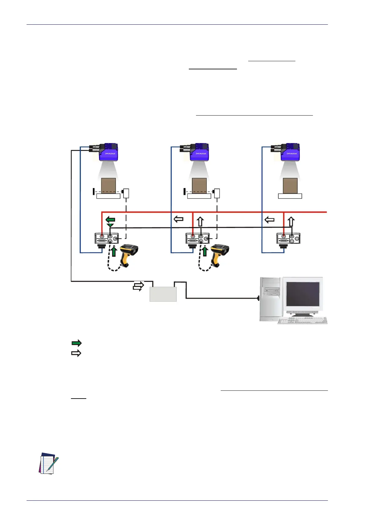
ID-NET Multidata Network (Pass-Through)
A special case of the pass-through layout allows each Slave device working
Alone to collect data from one or more pass-through
input channels and send
this data plus its own on the ID-NET
output channel to the Master.
The Slave readers are connected together using the ID-NET interface. Every Slave
re
ader must have an ID-NET address in the range 1-31.
The Master collects the data from its
pass-through ID-NET input channel and
sends it to the Host on a different output channel.
Host
CAB-DSxx-S
Phase
CAB-ETH-M0x
Ethernet TCP/IP Server 1
ID-NET (up to 32 devices, max network extension of 1000 m)
Main Serial Interface (RS232 or RS422 Full-Duplex)
Auxiliary Serial Interface (RS232)
Pass-through Input Channel
Output Channel
Alone
Alone Alone
Switch
Power
Mode
Continuous
Mode
External
Trigger
ID-NET
Master
ID-NET
Slave#1
ID-NET
Slave#2
Figure 66 - ID-NET Multidata Layout (Pass-through)
In a Pass-through layout each device supports multiple pass-through configura-
tions to accept input from different devices on different channels (i.e. Master
reader above). However, ID-NET Slave readers are not required to have a pass-
through configuration if they don’t need to receive data from an input channel
(i.e. right reader above). The ID-NET Master always has at least one pass-through
configuration to collect the ID-NET Slaves data and send it to the Host.
NOTE
Slave devices cannot receive data from a pass-through ID-NET input channel and
Master devices cannot send data on an ID-NET output channel.

 Loading...


