Outputs
Product Reference Guide 223
Outputs
Three general purpose non opto-isolated but short circuit protected outputs are
available on the M12 17-pin connector.
The pinout is the following:
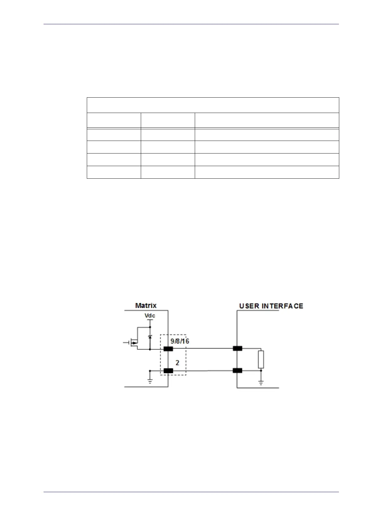
Output Pinout
Pin Name Description
9 O1 Configurable digital output 1
8 O2 Configurable digital output 2
16 O3 Configurable digital output 3
2 GND Output reference signal
The electrical features of the three outputs are the following:
Reverse-Polarity and Short-Circuit Protected
V
OUT
(I
LOAD
= 0 mA) max = 30 Vdc
V
OUT
(I
LOAD
= 100 mA) max = 3 Vdc
I
LOAD
max = 100 mA
The output signals are fully programmabl
e being determined by the configured
Activation/Deactivation events, Deactivation Timeout or a combination of the
two. For further details refer to the Help On Line page for the Output Setup step
in DL.CODE.
Figure 95 - PNP Output Connection