BM150 Display Module Configuration and Messages
Product Reference Guide 183
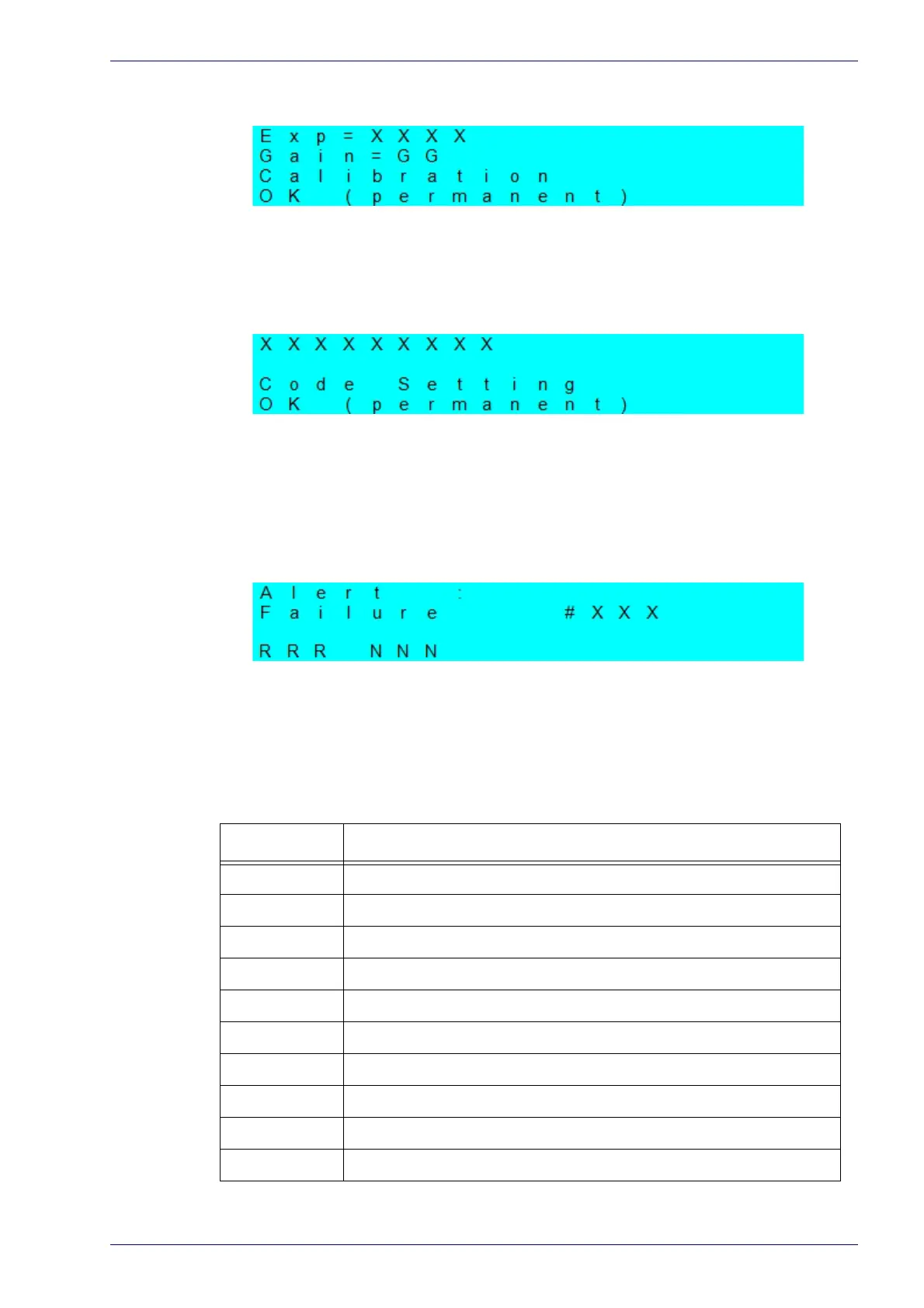
Calibration (Setup) Results:
X = exposure value (in s).
G = gain value
Code Setting (Learn) Results:
X = recognized code symbology.
Diagnostic Alarms:
Diagnostic error messages are sent to the BM150 display as numeric Alarm
Co
des (even if Failure Messages are selected for data transmission, the numeric
Alarm Code is sent to the display).
X = numeric Alarm Code (see below for the list of Alarm Codes)
R = Device Network Type – MUL=Multidata, SYN=Synchronized, ALN=Alone
N = Device Network Setting – M00=ID-NET Network Master, Sxx= ID-NET
Network Slave address
, Null string= Alone (no network)
Alarm Code Description
1 Slave No Reply
64 Slave Address Duplication
171 Protocol Index Failure
185 Backup Memory Communic
ation Failure
187 Wrong Rotary Switch Selection
189 Fieldbus Communication Failure
191 Fieldbus Type Mismatch
193 Fieldbus Configuration Error
195 Fieldbus DHCP Problem
201 No XRF Slave(s) Detected
 Loading...


