EasyManua.ls Logo

Datatool S4 Series - User Manual

Datatool S4 Series
57 pages
Print Icon
To Next Page IconTo Next Page
Loading...
S4 Series Training Manual
This manual is produced to support the training package provided by
Datatool (UK) Ltd
Due to the sensitive nature of its contents, Datatool (UK) Ltd specifically
forbid its contents to be copied or reproduced and transmitted to any third
party without the prior permission in writing of Datatool (UK) Ltd.
Any person(s) found to be in breach of this may find themselves removed
from the list of Datatool registered installers and subject to prosecution.
Contact details for Datatool (UK) Ltd
Tel: 0870 165 2414 Fax: 0870 165 2240
e-mail: info@datatool.co.uk
Website: www.datatool.co.uk

Table of Contents

Question and Answer IconNeed help?

Do you have a question about the Datatool S4 Series and is the answer not in the manual?

Summary

S4 Series Alarm Technical Specifications

Construction

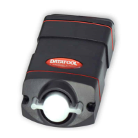
Details the physical build and materials of the S4 alarm unit.

Current Consumption

Provides electrical current draw data for various system states.

Specifying the System

Thatcham Approval Numbers

Lists Thatcham approval categories and corresponding model numbers.

Customer Decisions

Guidance for installers on discussing system options with customers.

Pre-Installation Checks

Installation Planning

Stripping the Machine

Procedures for safely dismantling motorcycle parts for alarm installation.

Mounting Techniques

Describes methods for physically securing alarm components.

LED Mounting and Wiring

LED Mounting Methods

Explains various ways to install the system's LED indicator.

Planning the Wiring

Outlines the process for planning the alarm system's electrical connections.

Connection Methods and Harnessing

The S4 Installation Tester

General Tester Instructions

Guidelines and warnings for using the S4 installation tester effectively.

Using the Installation Tester: Power & Starter

Main Power and Earth Connections

Testing positive and negative electrical connections using the tester.

Starter Cut Testing

Verifying the starter immobilisation circuit with the installation tester.

Using the Installation Tester: Engine & Ignition

Engine Cut Testing

Testing the engine immobilisation circuits using the installation tester.

Ignition Supply Testing

Verifying the ignition switched positive supply connection.

Using the Installation Tester: Indicators & Triggers

Indicator Connections and Testing

Testing the motorcycle indicator circuits with the installation tester.

ECU Protection Switch Testing

Testing the magnetic reed switch for ECU protection.

Secondary Trigger Circuit Testing

Testing the optional secondary trigger input using the tester.

Using the Installation Tester: Outputs & Commissioning

System LED Connections

Procedures for connecting and testing the system's LED indicator.

Supplementary Siren Output

Connecting and using the optional siren or pager output.

Transferring Wiring and Commissioning

Understanding Wire Functions

Main Power and Negative Connections

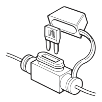
Explains the purpose of the main power and earth wires for system operation.

Immobilisation: Starter Cut

Details how the starter cut wires are used for immobilisation.

Understanding Wire Functions: Engine Cut

Understanding Wire Functions: AC Method

Understanding Wire Functions: Ignition Supply

Indicator Connections and Dioding

Indicator Connections

Guides on connecting the alarm to the bike's indicator circuits.

Dioding the Indicator Relay

Explains the necessity and method for installing diodes in indicator circuits.

Alarm Protection Switch

Secondary Trigger Circuit

Accessory Loop and Trigger Diagrams

System LED and Siren Outputs

System LED Connections

Procedures for connecting and testing the system's LED indicator.

Optional Supplementary Siren Output

Connecting and using the optional siren or pager output.

Combining Ignition Key with Remote Control

Combining Ignition Key with Remote Control (Cont.)

Operating Instructions

Credit Card Instructions

Basic system operation prompts for customer demonstration.

Disarming via PIN Code

Step-by-step guide for disarming the system using the PIN.

S4 Installer Operating Guide

Welcome and System Overview

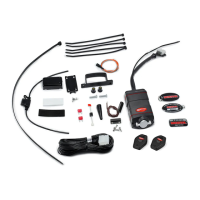
Introduction to the S4 system and its features.

System Registration (UK Only)

Process for registering the alarm system for warranty purposes.

Unique Transponder ID Tag

Information on the internal transponder tag for security and identification.

General Security Advice

The Remote Control

Remote Control Button Functions

Explanation of the functions controlled by the remote's buttons.

Changing Remote Control Battery: Red;Green

Changing Remote Control Battery: Yellow

System Arming Procedures

Passive Arming

How the system automatically arms after ignition is turned off.

Fully Arming the System

Steps to manually arm the system for full protection.

Ferry Mode Arming

Arming the system without the movement sensor activated.

System Disarming Procedures

Disarming After Trigger

How to disarm the system after it has been triggered, including fault codes.

Silent Arming;Disarming

Performing one-off silent arming or disarming operations.

Automatic Re-arming

How the system automatically re-arms itself if accidentally disarmed.

Special System Modes

Sleep Mode Function

Low power consumption modes to protect the motorcycle battery.

Hazard Warning Lights

Activating and deactivating the hazard warning lights feature.

Panic Locator Feature

Using the panic/locator function via the remote control.

The PIN Override System

Entering a New PIN Code

Procedure for setting a new personal identification number for the system.

Disarming the System with PIN

Adding Remote Controls & Software Switches

Adding Extra Remote Controls

Process for programming additional remote controls to the system.

Customising System Settings

Software Switch 1: Siren Tone

Adjusting the tone of the alarm's siren output.

Software Switch 2: Arming Settings

Configuring passive arming methods (immobiliser or full passive).

Software Switch 3: Engineer Switches

Engineers Software Switch Table

Transmitter Erase (Engineer Switch 1)

Removing old transmitter codes for security.

Engineer Switch 2: Reset Defaults

Engineer Switch 3: System Diagnostics

Engineer Switch 4: Movement Sensor Adjustment

Engineer Switch 5: Nudge Sensor Adjustment

Engineer Switch 6: Arm;Disarm Tones

Engineer Switch 7: Panic On;Off

Engineer Switch 8: Nudge Trigger Settings

Extending Security Features

Extra Siren;Pager Output

Connecting external sirens or pagers to the alarm system.

Covering Accessories

Using trigger inputs for accessories like luggage or side stands.

Garage Security

Integrating the alarm with a garage security kit for added protection.

Battery Management

Removing Motorcycle Battery

Procedures for safely removing the motorcycle battery while the alarm is installed.

Winter Mode Operation

Placing the system in low-power 'winter mode' for extended storage.

Service Support and Fault Finding

Transmitter Based Issues

Troubleshooting common problems related to the alarm transmitters.

Service Support and Fault Finding (Cont.)

Alarm Based Issues

Diagnosing and resolving problems originating from the alarm unit itself.

Installation and Machine Based Issues

System Current Usage

False Alarms Diagnosis

False Alarm Fault Finding Chart

A guide to identifying and resolving common false alarm triggers.

False Alarm Fault Finding Chart (Cont.)

Running Faults Diagnosis

Transmitter and Disarming Problems

Transmitter Design and Interference

Information on transmitter reliability and potential radio interference issues.

Voltage Based Issues

How battery voltage affects system features and disarming.

Lost or Stolen Transmitters

Procedure for removing lost or stolen transmitters from the system.

S4 Warranty System (Dattrac)

PIN Entry Procedure (Annex 1)

Programming Procedures (Annex 2)

Engineer Switch Functions (Annex 3)

S4 Series Immobilisation Systems

DC Immobilisation

Diagram and explanation for DC immobilisation wiring.

AC Immobilisation

Diagram and explanation for AC immobilisation wiring.

S4 Series Wiring Diagram (Annex 5)

Datatool S4 Series Specifications

General IconGeneral
Water ResistanceYes
Battery BackupYes
InstallationProfessional Installation Recommended
Power Supply12V
CompatibilityMost Motorcycles

Related product manuals