2: Installation
PRC1077-MSOP 2-19
8. Connect the C991614 cable to the MT-1077-24 adapter J1 connector (on
back), and to the UPF7000A-28, 28 Vdc power source and
ACLP-120-15, 120 Vac Surge Suppressor. Connect the ACLP-120-15
surge suppressor to 115 Vac power source.
9. Remove the rubber protective cap from the dual AUDIO connectors and
connect a military handset (MHS either H-189/U or M-250/U) to one of
the connectors.
Battery Charger Installation
The PRC1077 typically uses a BB-LA6 sealed lead-calcium rechargeable
battery pack that fits into the battery case. The battery case is attached to the
back of the transceiver case. The BB-LA6 battery can be recharged using the
following battery recharge configurations:
• PRC-PS Power supply/battery charger
• PRC-BC4 Multiple battery charger
• PRC-HC-30 Hand crank charger
• PRC-SPU-10 Solar power generator
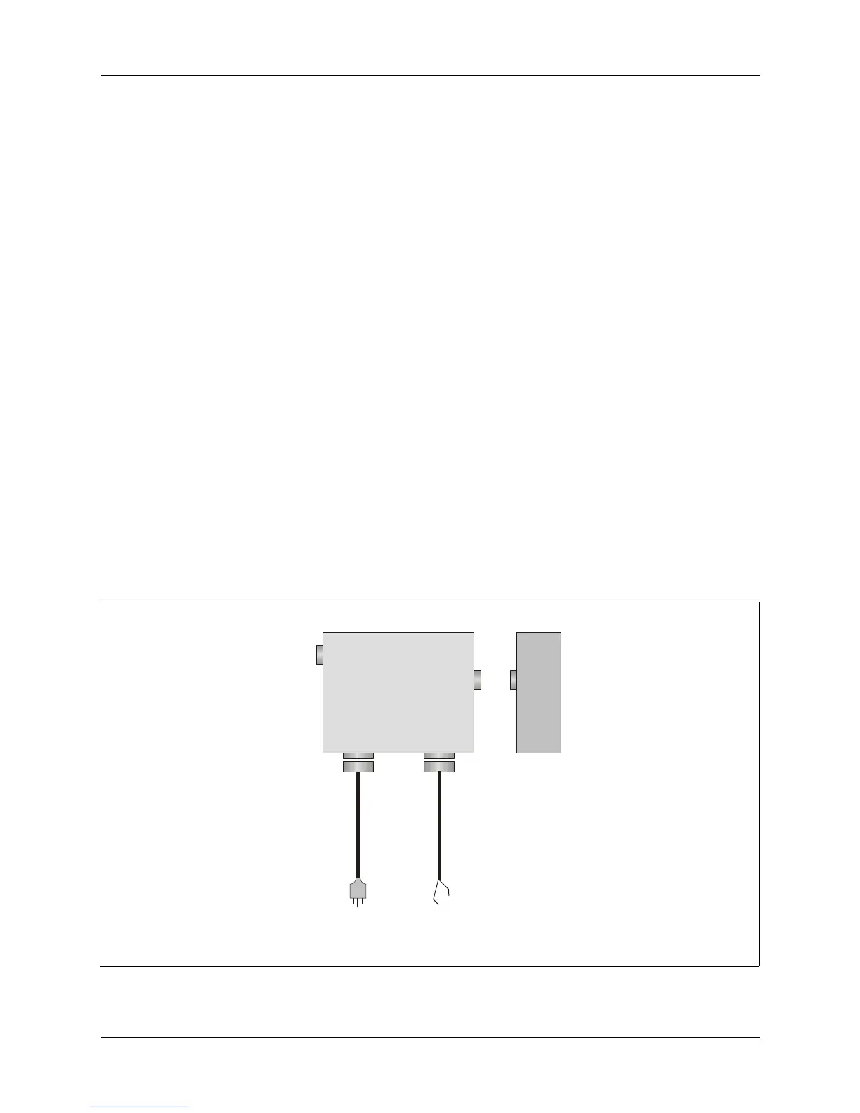
PRC-PS Power
Supply/Battery
Charger
The PRC-PS can operate both as an external power supply and as a battery
charger, powering a PRC1077 and recharging a BB-LA6 battery at the same
time. The PRC-PS does not provide power but derives power from either a
24 Vdc power source or a 115/230 Vac (internally strappable) power source.
Figure 2-11. PRC-PS Power Supply/Battery Charger
SET
PWR
AC
INPUT
DC
INPUT
J4
PRC-PS
BB-LA6
to
115/230 Vac
r
to
24 Vdc
source
C991609
J1
J3 J2