6: Power Amplifier Board
PRC1099A-MS 6-3
For final RF power amplifiers Q4 and Q5, the bias regulator circuit operates
the same as for the driver amplifiers. D2 senses the Q5 temperature and drives
bias regulator U4 at pin 3. U4 biases the base of Q7 up or down according to
the input FTSENS which drives RF power amplifiers Q4 and Q5. The
quiescent operating point for the final stage is set by adjusting R24.
6.1.5 Temperature Switch
The PA board includes a temperature-sensitive resistor (thermistor TH1) with
a positive temperature coefficient to prevent damage to RF power amplifiers
Q4 and Q5 from overheating. Thermistors change resistance with
temperature; this means that as the thermistor temperature increases, its
resistance increases. Bipolar transistor Q8 forms a voltage divider with TH1
and conducts when the heat sink temperature exceeds 80°C, pulling the LOW
POWER line to ground. This forces the radio RF power output to 5W or less
until the RF power amplifiers cools. TH1 is mounted in a hole in the board
heat sink under the PA board and normally measures about 150 ohms at room
temperature.
6.1.6 Specifications
Note: These specifications are subject to change without notice or
obligation.
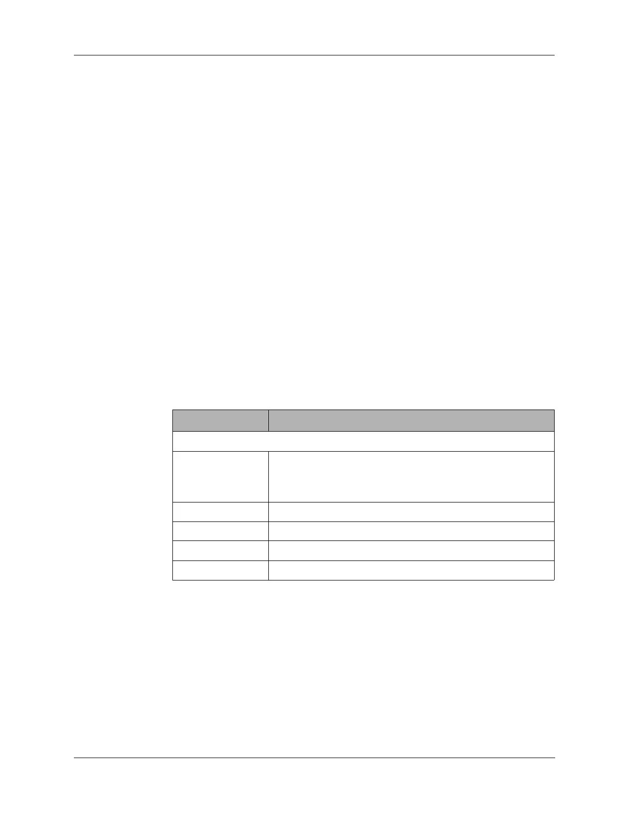
Table 6-1 Power Amplifier Board Specifications
Characteristic Description
Transmit
Current +8 VDC at 65 mA
+12 VDC at 250 mA (quiescent)
+12 VDC at 3.6A (20W, CW, output)
Frequency 1.6 to 30 MHz
Output 20W, CW into 50 ohm
Input 0 ±2 dB
Gain 43 dB