PRC1099A-MS 12-1
Chapter 12: Front Panel Assembly
The Front Panel assembly includes the front panel along with all the switches,
knobs and the LCD display.
12.1 Switches
12.1.1 Channel Switch
The Channel switch selects one of ten channels. Each channel number is
converted to a four-digit BCD code that is applied to input demultiplexer U14
on the Processor board through the Display board where the processor reads
the four BCD lines and selects the appropriate channel. These lines are held
high (+5V) until they are forced low by the BCD encoder within the switch,
therefore 0 = +5V and 1 = 0V.
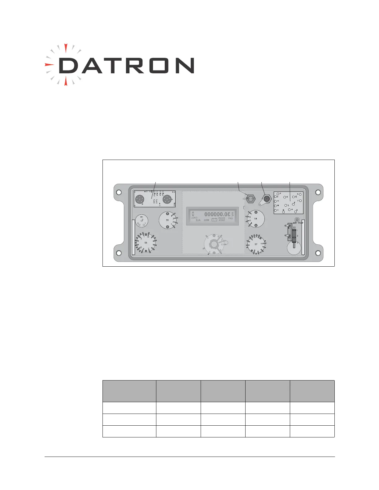
Figure 12-1 Front Panel Assembly (Rear View)
Audio
Connector
Board
Accessory
Connector
Board
Power
Switch
Digit
Whip
Antenna
Mode
Switch
Volume
GND
50 Ohm
Whip
Tune
Button
30.000000
OPT
<
SCAN
DATA
MSG
ALE
CALL
<
+
–
Display
Board
Channel
Switch
Tune
Table 12-1 Channel Switch BCD Code to Processor
Switch
Position
CHSWA CHSWB CHSWC CHSWD
MAN0000
1 1000
2 0100