10: Display Board
10-2 PRC1099A-MS
CAUTION: Do not switch on the backlight while working on the
display.
10.1.3 Jumpers
The Display board includes three jumpers: LK1, LK2, and LK3. Jumper LK1
is normally installed; the other jumpers are no longer used.
10.2 Connector Pin Assignments
The Display board has the following interconnections with the transceiver.
10.2.1 J1 Connector
J1 connects to the Processor board J5 connector.
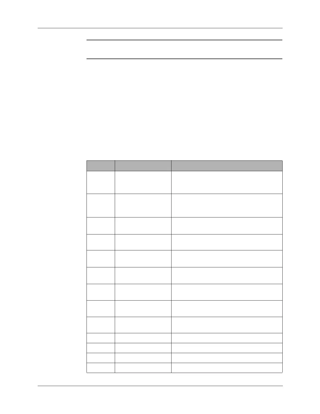
Table 10-1 J1 Connector Pin Assignments
Pin Signal Description
1OPTSW
Option switch line from front panel
MODE
switch (S6) to activate the AME option on the
Mixer board; connects to J4 pin 1.
2 LITE Turns on Q1, that turns on Q2 to enable LCD
backlight from front panel
MODE switch (S6)
in the
LITE position.
3 LSBSW Selects lower sideband from front panel
MODE switch (S6); connects to J4 pin 2.
4 +5V 5 VDC supply voltage from the Processor
board.
5SLEWDN
TUNE switch (S5) down position; connects
to J4 pin 3.
6SLEWUP
TUNE switch (S5) up position; connects to
J4 pin 4.
7 SQUELCH Enables squelch function from front panel
MODE switch (S6); connects to J4 pin 5.
8 DISDATA Display data line to Display board driver from
Processor board.
9 DISCLOCK Display clock line to Display board driver from
Processor board.
10 +12V 12 VDC supply voltage for the LCD backlight.
11 SPARE1 Connects to J4 pin 6 (open connection).
12 SPARE3 No connection.
13 SPARE2 Connects to J4 pin 7 (open connection).