7: Antenna Tuner Board
7-8 PRC1099A-MS
7.4 Component Locations, Schematics, and Parts List
This section provides a component location diagram, schematic and parts list
for the Antenna Tuner board.
5 +5V +5 VDC supply voltage from the Junction
board.
6 STROBE Strobes to shift registers from the Processor
board.
7 COMP OUT Comparator output to the Processor board, (for
tuning cycles).
8 ANT SW Antenna switch (0 VDC without antenna,
4.8 VDC with).
9, 10 No connection.
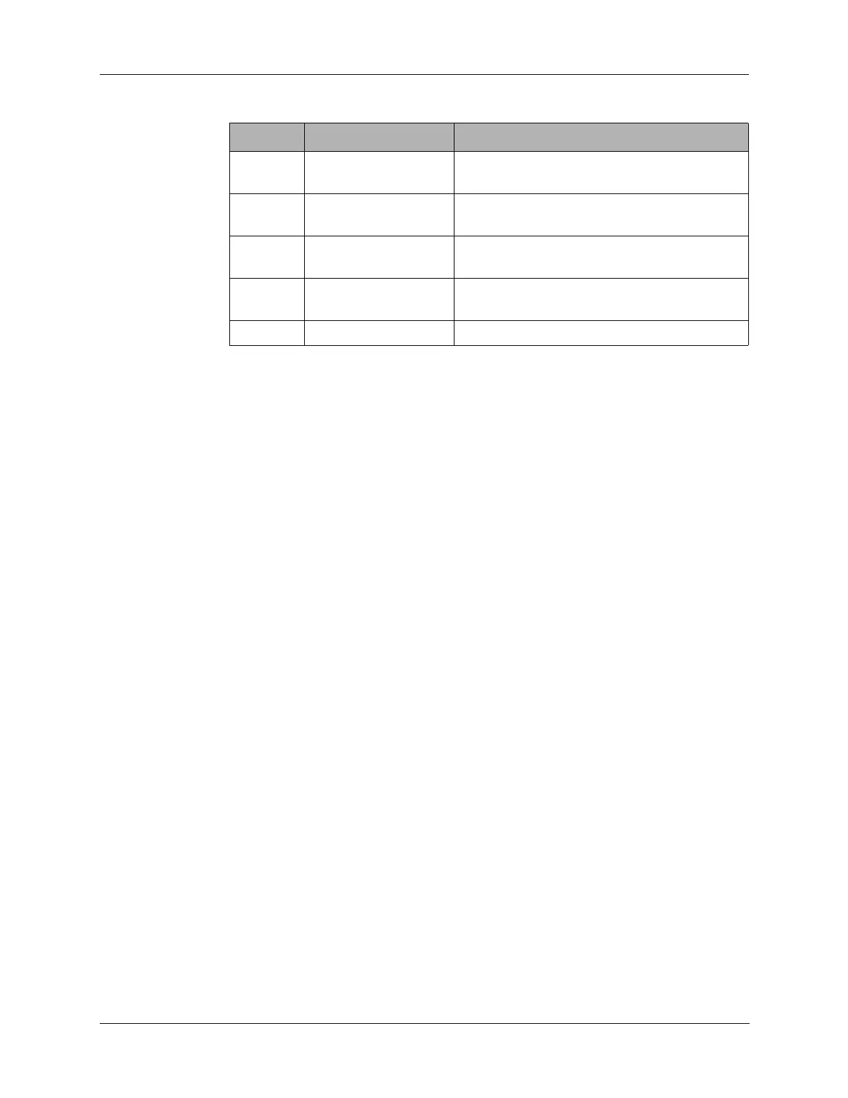
Table 7-2 J1 Connector Pin Assignments
Pin Signal Description