8: Synthesizer Board
PRC1099A-MS 8-5
8.2.2 J2 Connector
J2 is the coaxial connection that carries the first local oscillator frequency
(76.6 to 105 MHz) from the DDS to the Mixer board.
8.2.3 J3 Connector
J3 is the coaxial connection that carries the second local oscillator frequency
73.35 MHz or from the DDS to the Mixer board.
8.3 Component Locations, Schematics, and Parts List
This section provides a component location diagram, schematic and parts list
for the Antenna Tuner board.
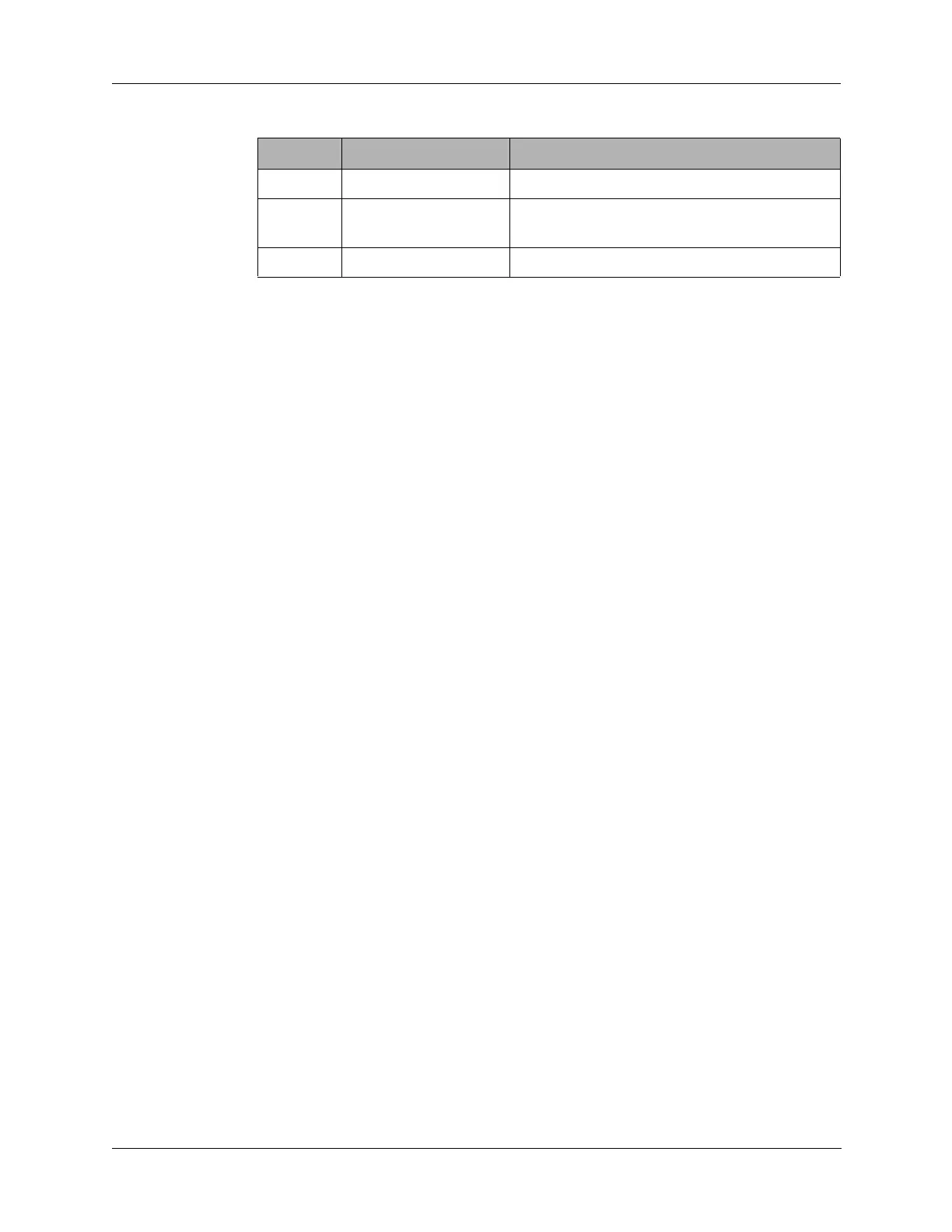
11 BFO_GND Ground for BFO coax.
12 BFO_OUT Coax output signal BFO/LO3
(1650/1647 kHz) to the Audio/Filter board.
13 BFO_GND Ground for BFO coax.
Table 8-2 J1 Connector Pin Assignments (continued)
Pin Signal Description