6: Power Amplifier Board
6-4 PRC1099A-MS
6.2 Connector Pin Assignments
The Power Amplifier board includes the following interconnections with the
transceiver:
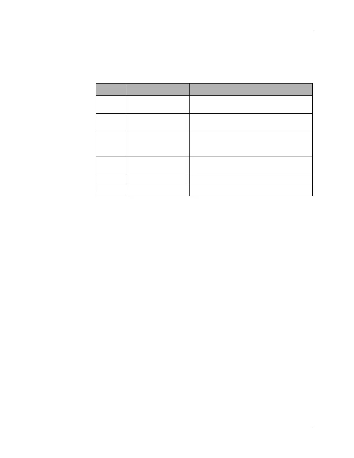
Table 6-2 J1 Connector Pin Assignments
Pin Signal Description
1 +12V 12 VDC supply voltage from the Junction
board.
2 +12V 12 VDC supply voltage from the Junction
board.
3 LOW POWER Line transitions low (0V) when the final
amplifiers overheat, otherwise +5V. This sets
the radio to low power (5W) mode.
4 T8 +8 VDC supply voltage when radio is in
transmit, 0 VDC in receive.
5 GND Chassis ground.
6 GND Chassis ground.