PRC1099A-MS 8-1
Chapter 8: Synthesizer Board
8.1 Circuit Description
The Synthesizer board generates three frequencies used to modulate,
demodulate, up-convert, and down-covert transmit and receive signals. The
variable first local oscillator is 76.6 to 105 MHz, depending on the channel
frequency, the fixed second local oscillator is 73.35 MHz, and the beat
frequency oscillator (BFO) is1650 kHz or 1647 kHz, depending on sideband
selection.
Note: Although the synthesizer is capable of 1 Hz resolution, the output
frequencies are limited to 10 Hz resolution.
The Synthesizer board includes the following major components:
• Reference oscillator at 100 MHz
• Four-channel direct digital synthesizer (DDS) device that generates all
three local oscillators (fourth channel is unused)
• PLL/Tracking filter that follows the LO output from the DDS
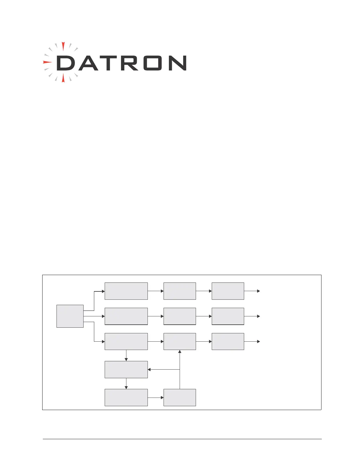
Figure 8-1 Synthesizer Board Block Diagram
DDS
BFO (1647 or 1650 kHz)
2nd LO (73.35 MHz)
1st LO (76.6–105 MHz)
LO2 Band
Pass Filter
LO1 Band
Pass Filter
ADF4002 Phase
Locked Loop
Loop Filter
BFO Band
Pass Filter
Amplifier
Amplifier
Amplifier
VCO
Low Pass
Filter
Low Pass
Filter
Low Pass
Filter