9: Processor Board
PRC1099A-MS 9-9
9.2 Connector Pin Assignments
The Processor board has the following interconnects with the Audio/Filter and
Display boards.
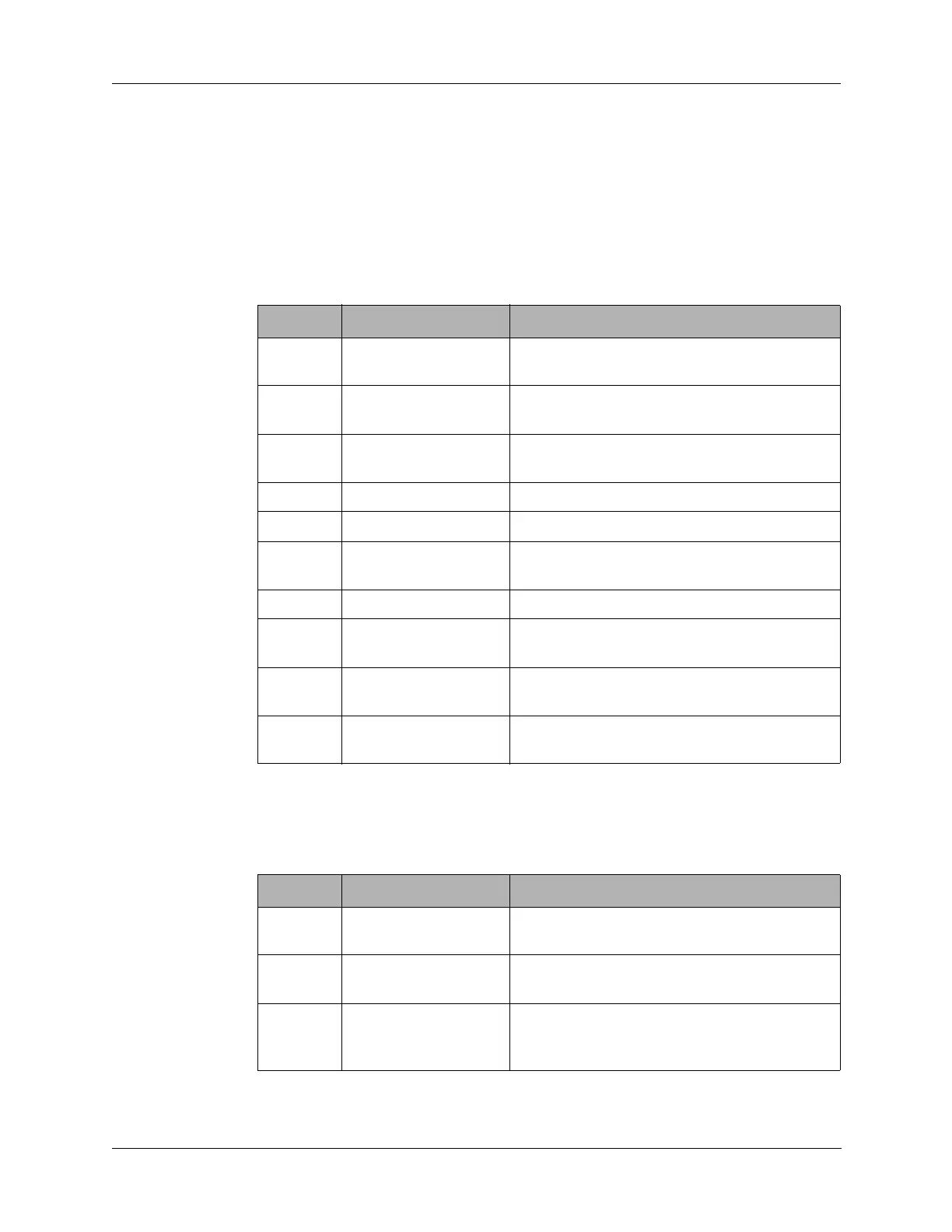
9.2.1 J1 Connector
J1 connects to J1 on the Audio/Filter board.
9.2.2 J2 Connector
J2 connects to the Audio/Filter board J2 connector.
Table 9-2 J1 Connector Pin Assignments
Pin Signal Description
1 AGC Automatic gain control from the 1650 kHz IF
board.
2 ALC Automatic level control from the Audio/Filter
board.
3 LOPWR Low power line from the front panel Power
switch (S7).
4 GND Ground.
5 GND Ground.
6 COMP Comparator output from the Antenna Tuner
board.
7 ENM5 Strobe line to the Antenna Tuner board.
8 ENM6A Enables latch clock for shift register on the
Synthesizer board.
9 ENM6B Enables address decoder on the Synthesizer
board.
10 ENM6C Enable line to Synthesizer board (open
connection on Synthesizer board).
Table 9-3 J2 Connector Pin Assignments
Pin Signal Description
1, 2 +5 +5 VDC supply voltage from the Junction
board through Audio/Filter board.
3 +12 +12 VDC supply voltage from the Junction
board through Audio/Filter board.
4 T8 Transmit 8 VDC supply voltage from the
Audio/Filter board (only available in transmit
mode).