9: Processor Board
9-10 PRC1099A-MS
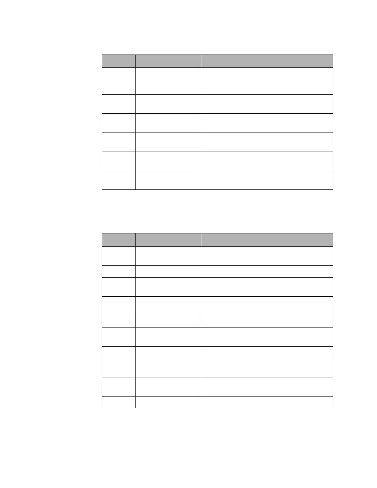
9.2.3 J3 Connector
J3 connects to the Audio/Filter board J3 connector
5 R8 Receive 8 VDC supply voltage from the
Audio/Filter board (only available in receive
mode)
6 +8 +8 VDC supply voltage from the Junction
board through the Audio/Filter board.
7 PTT +13.6 VDC in receive mode; 0 VDC in
transmit mode to Audio/Filter board.
8 DATA SPI data line to Audio/Filter, Synthesizer, and
Antenna Tuner boards.
9 CLOCK SPI clock line to Audio/Filter, Synthesizer,
and Antenna Tuner boards.
10 BITE Phase detector output from Synthesizer
board.
Table 9-3 J2 Connector Pin Assignments (continued)
Pin Signal Description
Table 9-4 J3 Connector Pin Assignments
Pin Signal Description
1 TX AUDIO FSK modulated ALE transmit tones to the
Audio/Filter board for an ALE call.
2 SPARE1 No connection on the Display board.
3 RX AUDIO Receive audio from the Audio/Filter board to
FSK modem U20 for an ALE call.
4 SPARE2 No connection on the Display board.
5 CWKEY CW tone (in transmit mode) from front panel
Audio connector to the Audio/Filter board.
6 CONTRAST LCD display contrast control from the
Audio/Filter board.
7 MUTE Mute control signal to the Audio/Filter board.
8 ENM1 Strobe line to shift registers U7 and U9 on
the Audio/Filter board.
9 VOICEDET Voice detect line from squelch circuit on the
Audio/Filter board.
10 RF DET No connection.