9: Processor Board
PRC1099A-MS 9-11
9.2.4 J4 Connector
J4 connects to the optional ALE board J1 connector.
9.2.5 J5 Connector
J5 connects to the Display J1 connector.
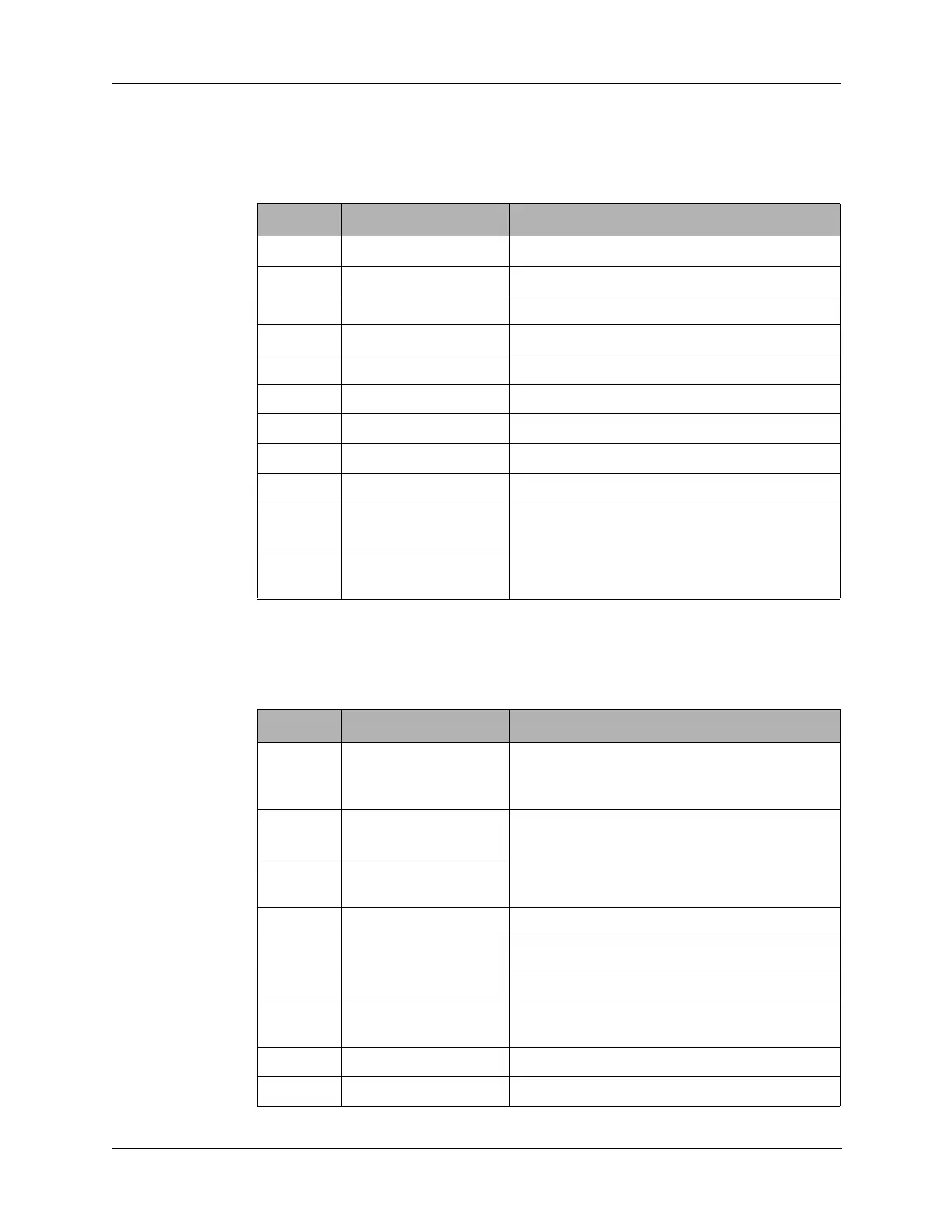
Table 9-5 J4 Connector Pin Assignments
Pin Signal Description
1, 2 +5 +5 VDC from the Junction board.
3, 4 GND Digital ground.
5, 6 GND Analog ground.
7 ALERST ALE reset to the ALE board.
8 to 14 NC No connection.
15 KEYLINE PTT input from on the ALE board.
16 ALEPTT ALE PTT output to the ALE board.
17 SCRXD ALE serial data receive from the ALE board.
18 SCTXD ALE serial data transmit to the ALE board.
19 ALERXA Receive audio from the Audio/Filter board to
the ALE board.
20 ALETXA FSK modulated ALE transmit audio to the
ALE board.
Table 9-6 J5 Connector Pin Assignments
Pin Signal Description
1 OPTSW Option switch line from front panel Mode
switch (S6). Activates the AME option on the
Mixer board.
2 LITE Enables LCD backlight from front panel Mode
switch (S6) in the
LITE position.
3 LSBSW Selects lower sideband from front panel
Mode switch (S6).
4 +5 5 VDC supply voltage to the Display board.
5SLEWDN
TUNE switch (S5) down position.
6SLEWUP
TUNE switch (S5) up position.
7 SQUELCH Enables squelch function from front panel
Mode switch (S6).
8 DISDATA Display data line to Display board driver.
9 DISCLK Display clock line to Display board driver.