11: Junction Board
11-2 PRC1099A-MS
11.2 Connector Pin Assignments
The Junction board has the following interconnections with the transceiver.
11.2.1 J1 Connector
J1 connects to multiple boards including the Audio/IF board, Mixer board,
Synthesizer board, Antenna Tuner board, 1650 kHz IF board, and the Power
Amplifier board. It also connects to the front panel power switch (S7).
11.2.2 J2 Connector
J2 connects to multiple boards including the Audio/IF board, Mixer board,
Synthesizer board, Antenna Tuner board, and the Power Amplifier board.
11.2.3 J3 Connector
J3 connects to the front panel Power switch (S7) and the battery or DC power
source.
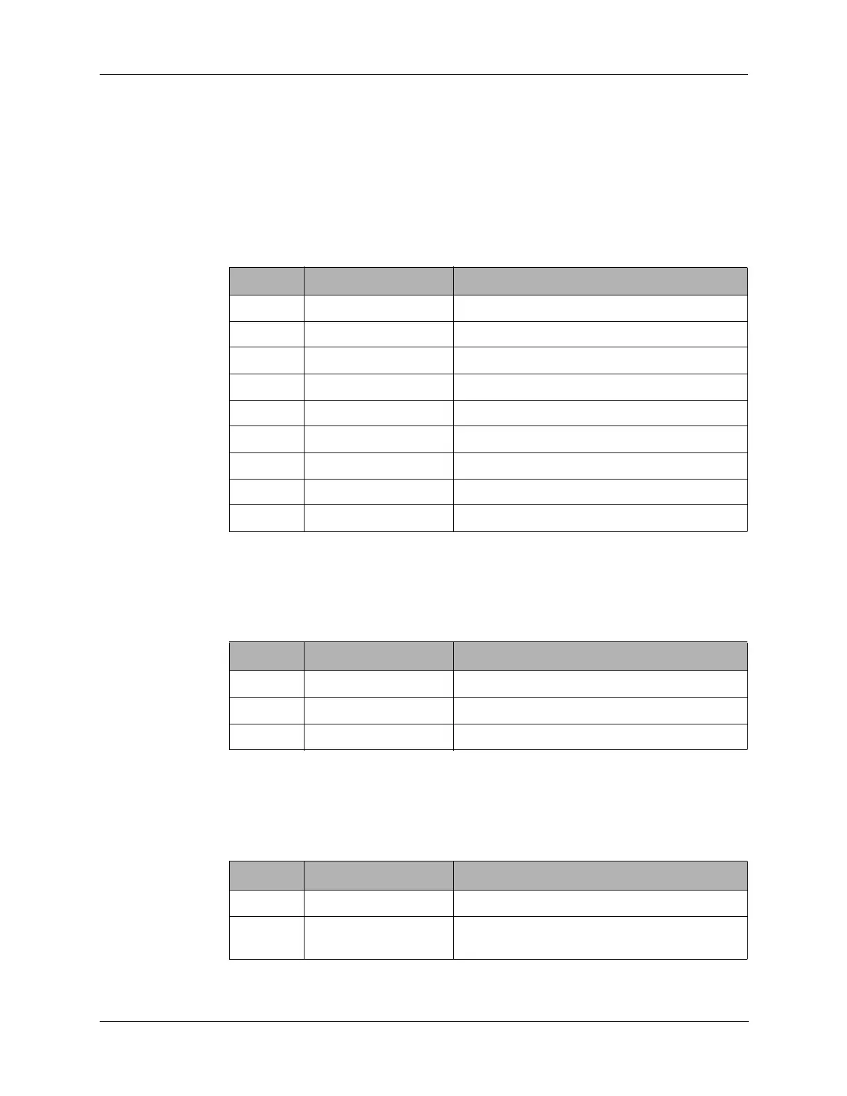
Pin Signal Description
1 BAT CHG OUT Not used.
2 BAT CHG OUT Not used.
3 BAT CHG IN Not used.
4 BAT CHG IN Not used.
5 to 7 AGC Jumpered AGC lines.
8 to 12 T8 Interconnections for T8 line
13 to 16 R8 Interconnections for R8 line
17 +5V +5 VDC supply voltage
20 +5V +5 VDC supply voltage to Synthesizer only
Table 11-1 J3 Connector Pin Assignments
Pin Signal Description
1 to 5 +8V +8 VDC supply voltage
6 to 12 +12V +12 VDC supply voltage
13 to 20 GND Interconnections for ground
Table 11-2 J3 Connector Pin Assignments
Pin Signal Description
1 GND Ground to battery.
2 +12V Switched +12 VDC supply voltage from front
panel power switch.