10: Display Board
PRC1099A-MS 10-3
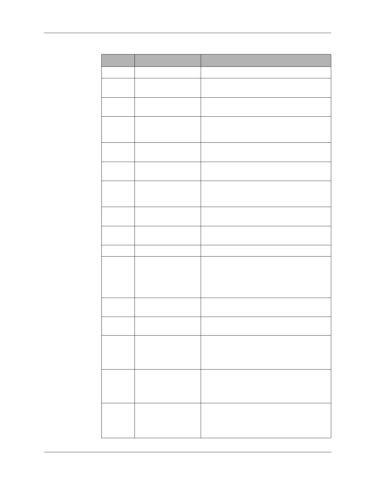
14 GND Ground.
15 CWKEY CW Key line from both front panel Audio
connectors; connects to J4 pin 8.
16 PTT PTT from front panel Audio connectors and
Accessory connector; connects to J4 pin 9
17 CONTRAST Contrast control from the Audio/Filter board,
sets contrast of LCD display to display driver
U1.
18 EXTSEL External amplifier RA100 filter select line;
connects to J3 pin 4.
19 DIGDN Digital knob down position line; connects to
J3 pin 5.
20 TUNEINIT Initiates tune cycle to RAT7000B antenna
tuner through front panel Accessory
connector pin D; connects to J3 pin 6.
21 ANTSW From internal antenna switch in the Whip
Antenna connector; connects to J3 pin 7.
22 CHSET/TUNE From the front panel Whip tune button;
connects to J3 pin 8.
23 HANDSET Not used; connects to J3 pin 9.
24 ALC ALC line to a RA100 external RF amplifier
through the front panel Accessory connector
pin N. ALC signal from the RA100 ALC
activates PRC1099A ALC circuitry; connects
to J3 pin 10.
25 DIGUP From front panel DIGIT switch (S4) up
position; connects to J2 pin 1.
26 AMPPTT PTT to RA100 external amplifier; connects to
J2 pin 2.
27 RS232TXD Serial data line to external RA100 amplifier or
RAT7000B antenna tune. Also serial TX line
for remote control terminal; connects to J2
pin 3.
28 RS232RXD Serial clock line to external RA100 amplifier
or RAT7000B antenna tuner. Also serial RX
line for remote control terminal; connects to
J2 pin 4.
29 EXTAMP
From the front panel
POWER switch (S7)
LO power position. Sets to radio to low RF
output power (5W) for use with external
amplifier RA100; connects to J2 pin 5.
Table 10-1 J1 Connector Pin Assignments (continued)
Pin Signal Description