12: Front Panel Assembly
12-2 PRC1099A-MS
12.1.2 Power Switch (S7)
The Power switch applies DC power to the radio and sets the RF output power
to either
LO (5W), HI (20W), or selects an external RF power amplifier in the
EXT AMP position.
OFF Position The Power switch receives +12V battery voltage from the Junction board
through the Accessory connector jumper (must be installed). In all positions
except
OFF, it switches the +12 V back to the Junction board where it is
converted to +8V and +5V supply voltages.
3 1100
4 0010
5 1010
6 0110
7 1110
8 0001
9 1001
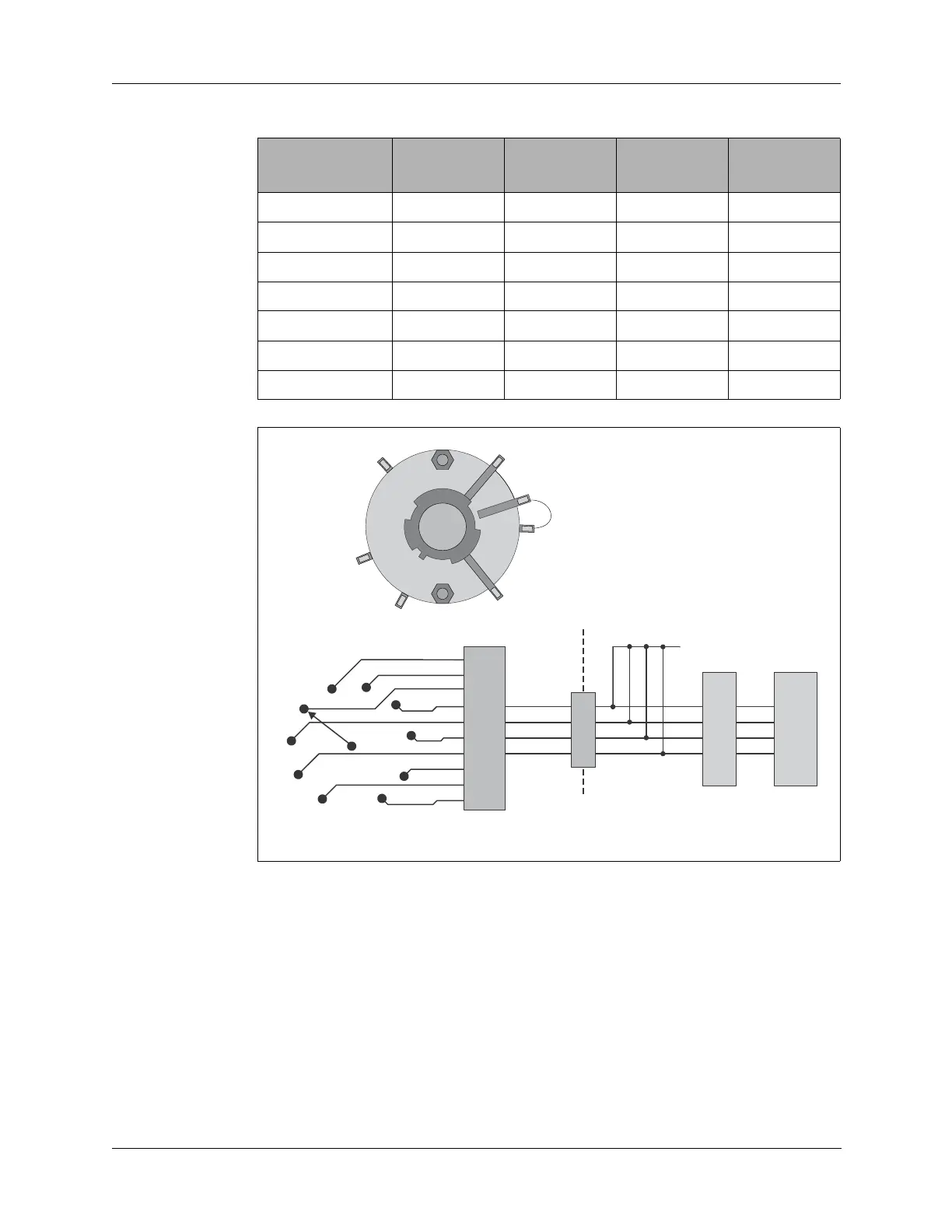
Figure 12-2 Channel Switch (S1) Diagram
Table 12-1 Channel Switch BCD Code to Processor (continued)
Switch
Position
CHSWA CHSWB CHSWC CHSWD
CHANNEL
SWITCH
S1
4
1
2
MAN
3
9
8
7
6
5
9
M
8
1
7
6
2
3
5
4
C
D
A
B
CHSWA
CHSWB
CHSWC
CHSWD
D
A
C
B
E
E2
Processor
Board