12: Front Panel Assembly
PRC1099A-MS 12-3
LO Power
Position
In the LO position, the Power switch grounds the LOPWR signal that passes
through the Display board and is applied to input demultiplexer U14 on the
Processor board. The processor reads the 0V level on the LOPWR line and
activates low power switch Q22 on the Audio/Filter board to lower the RF
output power to 5W (refer to “Low Power Switch” on page 3-6).
HI Power
Position
The HI position is the normal operating mode for the radio. The Power switch
connects the +12V BATTERY line from the Junction board, through the
Accessory connector jumper to the +12V SWITCHED line on the Junction
board. This is the same for all positions on the Power switch except the OFF
position. This supplies 12V to the radio.
EXT AMP
Position
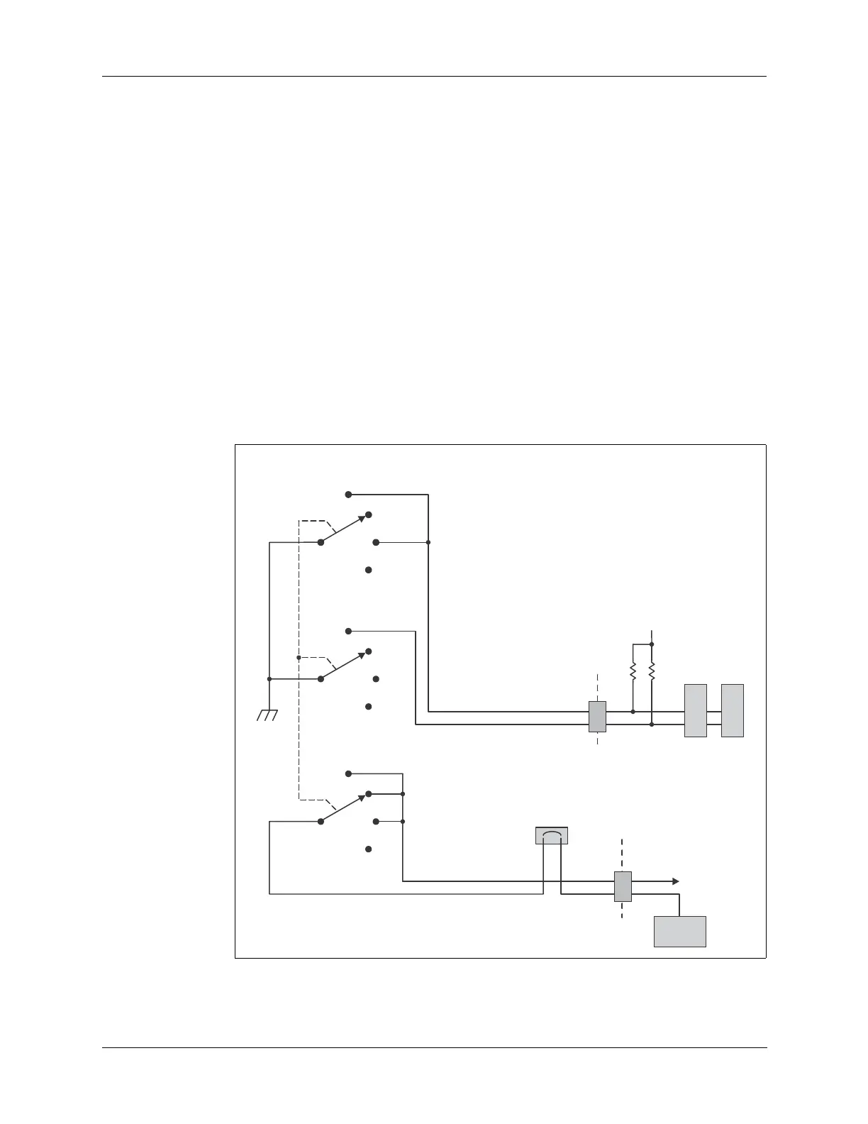
The EXT AMP position function is identical to the LO position as shown in
Figure 12-3 below except that the EXTAMP line is grounded through the
Power switch center conductor. When the Power switch is set to EXT AMP,
the radio outputs approximately 5W as in low power mode. If external
amplifier RA100-12/24 is connected to the front panel 50 Ohm output
connector, it boosts the RF power to the antenna to 100W.
Figure 12-3 Power Switch Diagram
EXT AMP
HI
LO
OFF
Power Switch
S7
+12V
+12V JUMPERED
LOPWR
EXTAMP
+12V SWITCHED
+12V