12: Front Panel Assembly
12-4 PRC1099A-MS
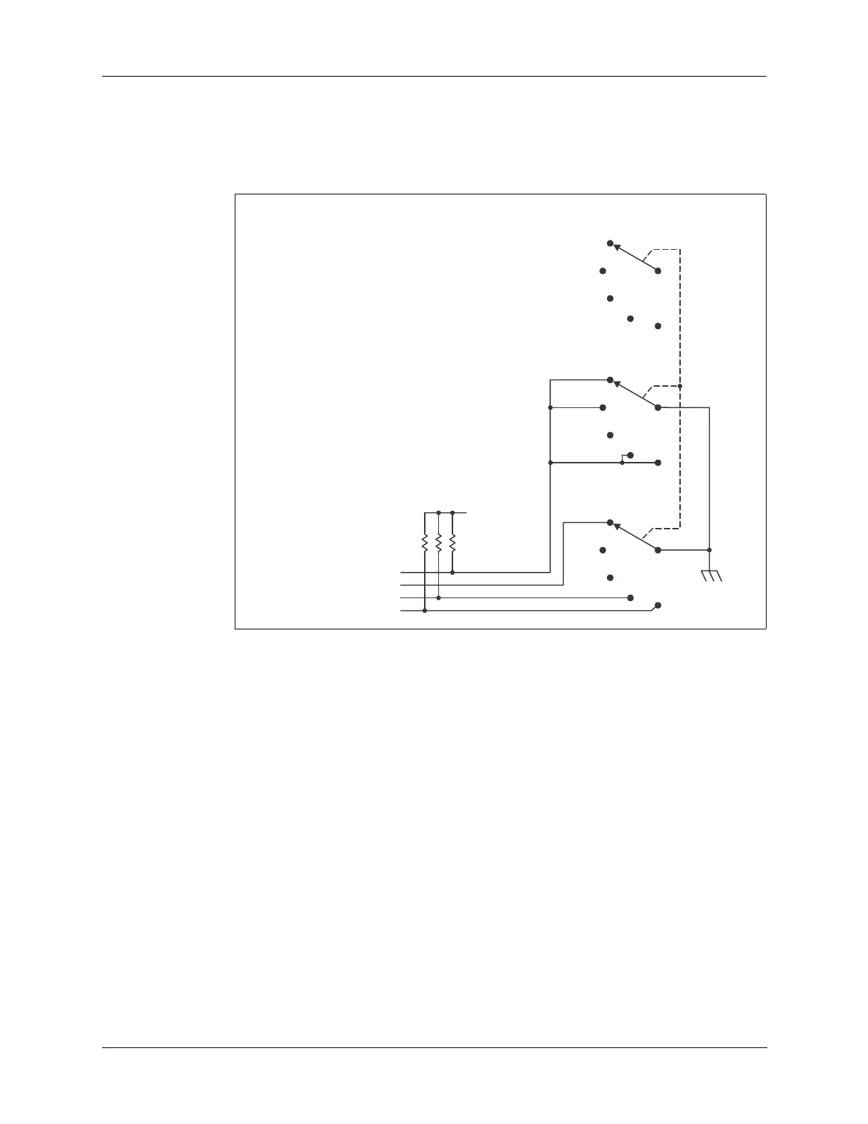
12.1.3 Mode and Option Switch
The front panel Mode and Option switch selects between upper sideband
(UPS) and lower sideband (LSB) modes, squelch, and the option switch that
selects the AME option mode as shown in Figure 12-4 below.
LITE Position The LITE position switches on the LCD display backlight on the Display
board (refer to “Backlight Generator” on page 10-1). Through the center
conductor, the Mode and Option switch grounds the FPLITE line to the
Display board energizing the LCD display backlight.
USB Position The USB position selects upper sideband operation. USB is the normal
operation mode, which means that in all positions except LSB, the radio
operates in USB mode. In the USB position, the Mode and Option switch is
open except for the SQUELCH line—no lines except the SQUELCH line are
grounded.
SQUELCH
Position
The SQUELCH position activates the squelch circuit on the Audio/Filter
board through the processor on the Processor board. The squelch function
mutes the receive audio except when a voice signal is detected. This removes
background hiss between received spoken words and sentences.
Through the center conductor, the Mode and Option switch opens the
SQUELCH line—the SQUELCH line is grounded in all other modes. The
opened SQUELCH line is pulled high on the Processor board and applied to
Figure 12-4 Mode and Option Switch Diagram
to Processor board J5 pin 1
to Processor board J5 pin 3
to Display board J4 pin 10
to Processor board J5 pin 7
+5V