9: Processor Board
9-2 PRC1099A-MS
9.1.1 Processor
Processor U1 is combined with the input/output circuits to form a special
purpose microcomputer. It controls the operation of the transceiver in
response to the control inputs, in accordance with the program stored in
memory.
The processor is a Motorola MC68302 that uses a 68000 processor core. This
processor has the capability of addressing up to 2 Mb of EPROM memory and
64 kB of static RAM for future program expansion. It also has three UARTS,
two timers, 18 bidirectional input/output lines, and four external interrupt
sources.
The processor operates at a clock frequency of 4 MHz and uses an internal
oscillator controlled by Y1. UART1 provides RS-232 communications
through the front panel Accessory connector. UART2 communicates with the
optional ALE card.
PA2 through PA7 drive the control bus, while PA10 through PA14 are for the
d-mux bus. PA15 and PB0 through PB4 are for miscellaneous control
functions.
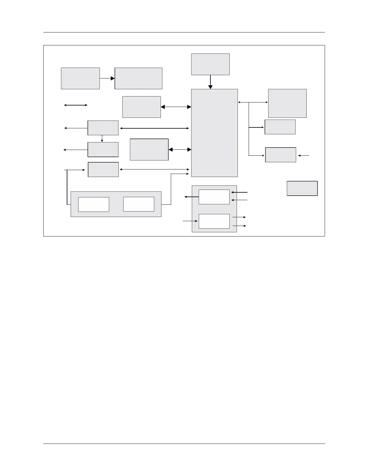
Figure 9-1 Processor Board Block Diagram
RS-232
COMMS
Control
Bus
Processor
Control
Inputs
Control
Inputs
GP12
ALE TX
Audio
ALE RX
Audio
TA TX
Audio
TA TX
Audio
Oscillator
RS-232
I/O
Control
Bus
Outputs
Control
Outputs
Input
Demultiplexer
Microprocessor
Controller
Memory
Backup
System
ALE
Switch
EPROM
Audio Buffers
TX
Interrupt
Signaller
State
Change
Detector
Wake up Control