10: Display Board
PRC1099A-MS 10-5
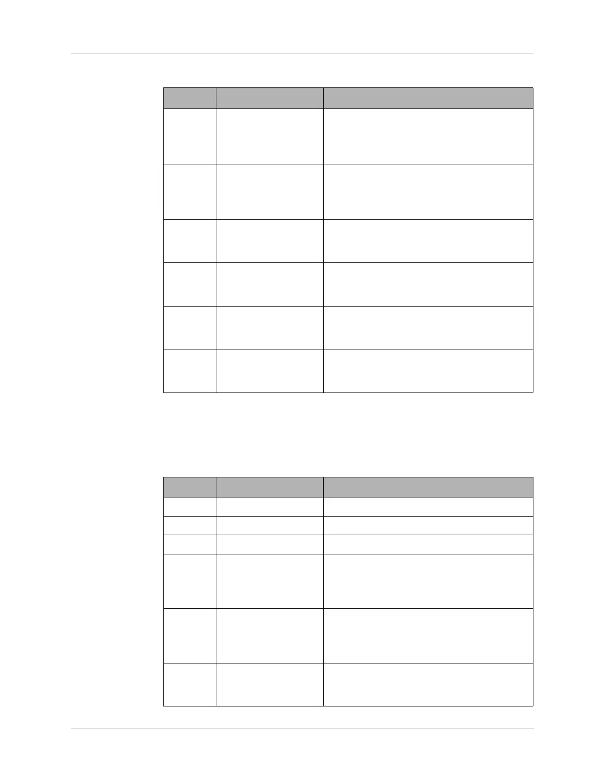
10.2.3 J3 Connector
J3 connects to the front panel Accessory connector, Audio connector, Channel
tune switch. None of the pin assignments have onboard connections.
5 EXTAMP Connects J1 pin 30 to ground through the
front panel
POWER switch (S7) LO power
position. Sets to radio to low RF output power
(5W) for use with external amplifier RA100.
6 LOPWR Connects J1 pin 30 to ground through the
front panel
POWER switch (S7) LO power
position. Sets to radio to low RF output power
(5W).
7 CHSWA Connects J1 pin 31 to front panel
CHANNEL switch (S1) for the A-bit in 4-bit
BCD code for channel selection.
8 CHSWB Connects J1 pin 32 to front panel
CHANNEL switch (S1) for the B-bit in 4-bit
BCD code for channel selection.
9 CHSWC Connects J1 pin 33 to front panel
CHANNEL switch (S1) for the C-bit in 4-bit
BCD code for channel selection.
10 CHSWD Connects J1 pin 34 to front panel
CHANNEL switch (S1) for the D -bit in 4-bit
BCD code for channel selection.
Table 10-2 J2 Connector Pin Assignments (continued)
Pin Signal Description
Table 10-3 J3 Connect Pin Assignments
Pin Signal Description
1 GND Ground.
2 BC IN Not used.
3 OPTION PIN Not used.
4 EXTSEL Connects J1 pin 18 to the RA100 external RF
amplifier through front panel Accessory
connector pin M to select the appropriate
filter.
5 DIGDN Connects J1 pin 19 to ground when the front
panel
DIGIT switch is pushed to the down to
select menus or alphanumeric digits. Moves
the highlight left on the LCD.
6 TUNEINIT Connects to J1 pin 20 to a RAT7000B
antenna tuner through front panel Accessory
connector pin D to initiate a tune cycle.