13: Internal Options
13-2 PRC1099A-MS
13.1.1 Operation
The ALE functions are all operator-accessible through the front panel menu
system. All menu selections for the ALE option are described in the
PRC1099A Operator manual (PRC1099A-MSOP).
13.1.2 Circuit Description
The ALE board contains a main processor and a DSP processor. Figure 13-1
on page 13-1 provides a block diagram of the ALE board. The following
sections describe the main Processor board components.
Main ALE
Processor
Main ALE processor U3 is combined with the input/output circuits to form a
special purpose microcomputer. The main ALE processor processes the ALE
data received from the DSP. It also prepares the ALE data before it is sent to
the DSP for transmission.
This processor can address up to 64 kilobytes of EPROM memory and 64
kilobytes of static RAM for future program expansion. It also includes one
UART, two timers, 32 bi-directional input/output lines, and six external
interrupt sources.
The main processor operates at a clock frequency of 11.0592 MHz derived
from external oscillator U2. The UART communicates with the main radio
processor through serial buffers.
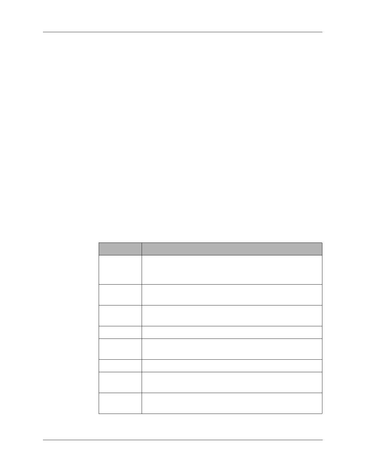
P1 ports provide the following control functions:
Port Function
P1.0
Selects the communications mode for the external serial
control interface. This interface is strictly for processor
control or control through an external dumb terminal.
P1.1
Sets the serial control interface baud rate of 9600 or 19200
baud.
P1.2
Keyline output drive for keying the PTT line of an external
device
P1.3
Input used to read the current status of the PTT line.
P1.4
Provides the processor watchdog output to reset controller
chip U1.
P1.5
Provides a control input into the DSP processor.
P1.6
Monitors the dual port RAM interrupt going to the DSP
processor.
P1.7
Provides the DSP processor reset pulse for a controlled
power up of the DSP processor.