4: 1650 kHz IF Board
4-4 PRC1099A-MS
4.2 Connector Pin Assignments
The 1650 kHz IF board has the following connections: J1, J2, J3, and J4.
4.2.1 J1 Connector
J1 connects with the Audio/Filter, the Junction, and the Mixer boards.
4.2.2 J2 Connector
Coax connector J2 (TX IN) carries the transmit signal from the Audio/Filter
board.
4.2.3 J3 Connector
Coax connector J3 (1650 I/O) carries the transmit output signal to the Mixer
board and the receive input signal from the Mixer board.
4.2.4 J4 Connector
Coax connector J4 (RX OUT) carries the receive signal to the Audio/Filter
board.
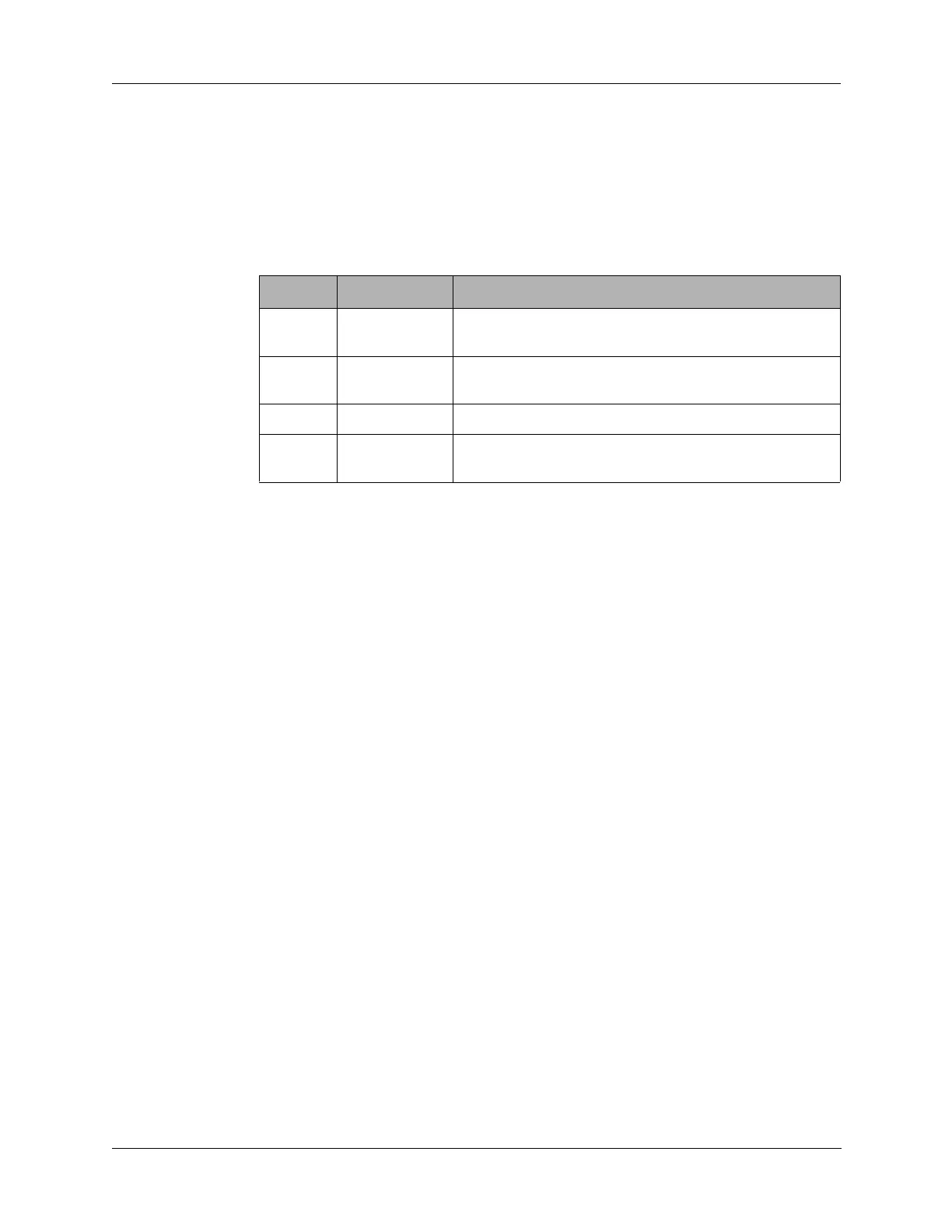
Table 4-2 J1 Connector Pin Assignments
Pin Description Connection
1 AGC Automatic gain control for setting the audio level in
receive mode to the Mixer board. Typically 4 VDC
2 R8 +8 VDC when radio is in receive mode, 0 VDC in
transmit mode from the Audio/Filter board.
3 +8V +8 VDC from power supply from the Junction board.
4 T8 +8 VDC when radio is in transmit mode, 0 VDC in
receive mode from the Audio/Filter board.
 Loading...

