5: Mixer Board
5-8 PRC1099A-MS
5.2 Connector Pin Assignments
The Mixer board has the following interconnections with the transceiver.
5.2.1 J1 Connector
J1 connects to the Junction, Audio/Filter, and 1650 kHz IF boards.
Receive
Current 8 VDC at 20 mA
8 VDC at 12.5 mA (squelched)
12 VDC at 17.5 mA
12 VDC at 5.7 mA (squelched)
Output 1650 kHz
Input Channel frequency (Fs)
Gain 32 dB
Oscillators
Level at TP1 +7 dBm at 76.6 to 105 MHz
2 Vrms at 73.35 MHz
Level at U2-10 2 Vrms at 73.35 MHz
Level at U2-10 100 mVrms at 73.35 MHz
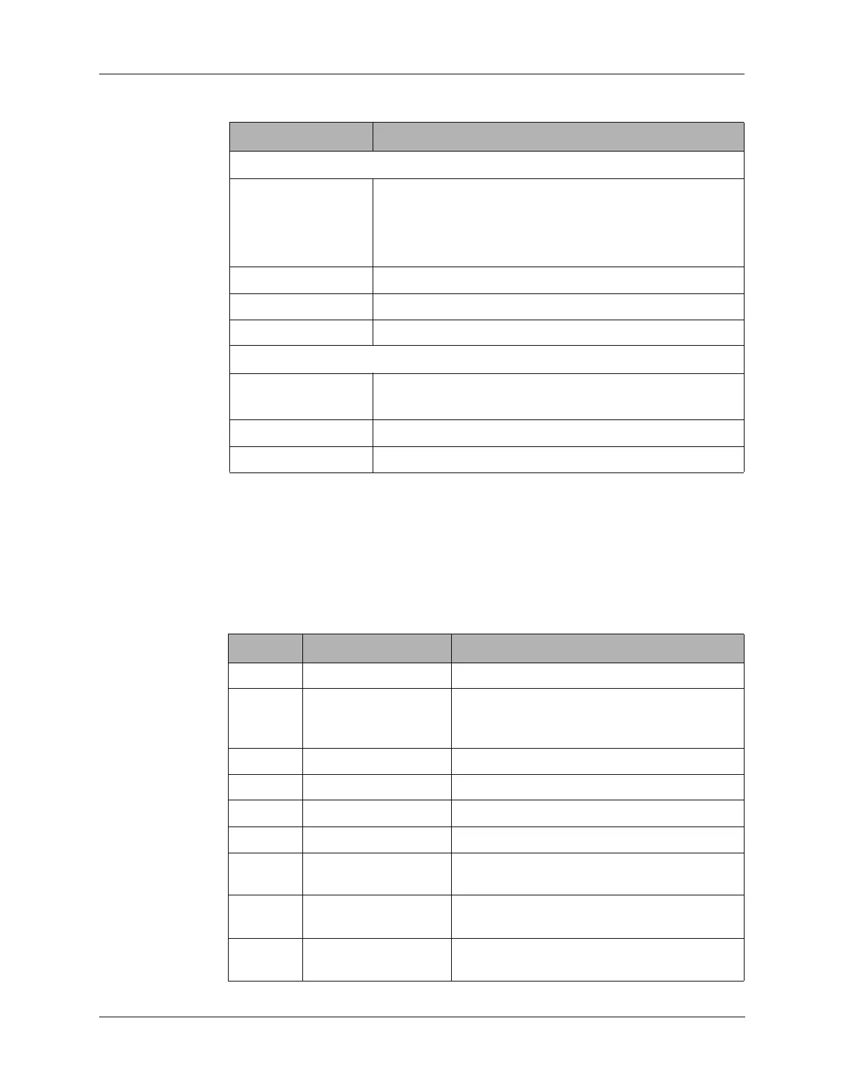
Table 5-1 Mixer Board Specifications (continued)
Characteristic Specification
Table 5-2 J1 Connector Pin Assignments
Pin Signal Description
1 GND Chassis ground.
2 ALC Automatic level control from the Audio/Filter
board for setting the output power level in
transmit mode.
3 +12V 12 VDC from the Junction board.
4 +8V 8 VDC from the Junction board.
5 R8 8 VDC in receive from Audio/Filter board.
6 T8 8 VDC in transmit from Audio/Filter board.
7 SQUELCH Squelch signal from the Audio/Filter board to
disable receive audio.
8 AGC Automatic gain control from the 1650 kHz IF
board for setting audio level in receive mode.
9 AME For enabling AME option, when installed, from
the Audio/Filter board.