24
Installing the Sensor Suite and Anemometer on a Flat
Surface
Install the rain collector mounting base:
1. With a 3/16" (5 mm) drill bit, drill two holes approximately 2
1
/
8
" (54 mm) apart.
Use a carpenter’s level to ensure the holes are level.
Use the metal backing plate as a guide when marking the holes.
2. Remove the rain collector cone if it is installed on the sensor suite mounting base.
3. Insert the 1/4" x 3" lag screws through the metal backing plate and the holes in the
mounting base into the post. Make sure the sensor suite is level by checking the
built-in bubble level.
4. Tighten the lag screws using an adjustable wrench or 7/16" wrench.
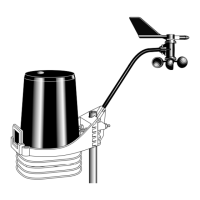
Install the Anemometer
1. With a 3/16" (5 mm) drill bit, drill two holes approximately 2
1
/
8
" (54 mm) apart.
Use a carpenter’s level to ensure the holes will be level.
2. Insert the 1/4" x 3" lag screws through the flat washers and the holes in the
anemometer mounting base into the post.
3. Tighten the lag screws using an adjustable wrench or 7/16" wrench.
Note: If your anemometer arm cannot be mounted aiming true north, you will need to
calibrate the wind direction on your Console to display accurate wind directions. See
your WeatherLink Console User Guide.
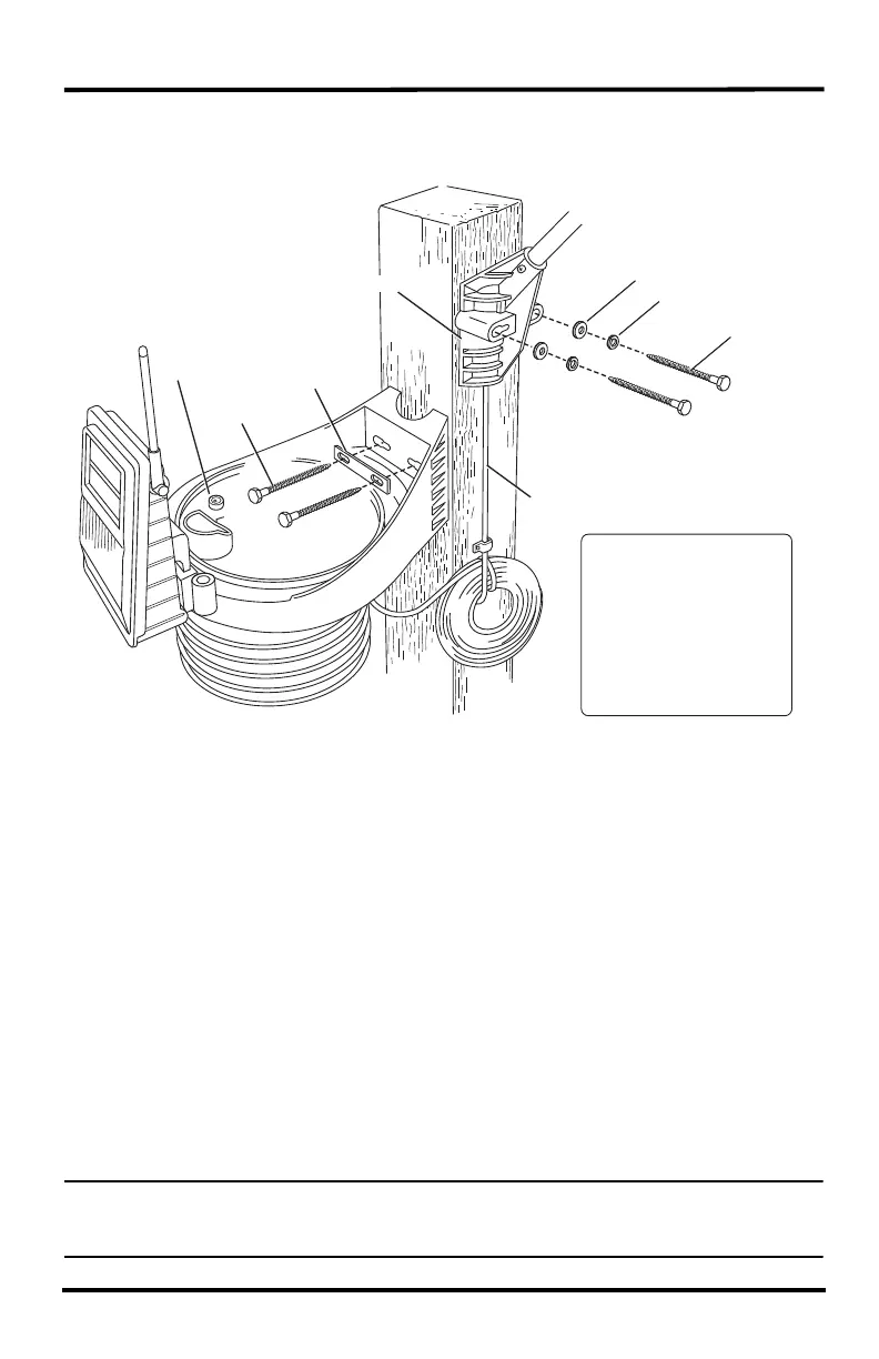
Backing Plate
Bubble
Level
1/4" x 3"
Lag Screws
1/4" Flat Washers
1/4" Lock Washers
1/4" x 3" Lag Screws
Anemometer Base
40' of Anemometer Cable
Note: Typically, the
anemometer and rain
collector are mounted on
opposite sides of the post.
They are shown mounted
on adjoining sides to
clarify the installation
details.
Tipping spoon not
shown for clarity.