25
After entering Service Mode, the rst number that you will see indicates the software model number for the particular unit you are
servicing.
Model Description Software Model Number
RF242D 24 inch Refrigerated Drawers 17
The second number you will see indicates the software version release. For example, if you see 39 on the display panel it indicates
software version 3.9 and 41 indicates software version 4.1.
Diagnostics:
While in Service Mode, press the “SET” button to step through Tests 0-9. The rst digit of the display will show the test number.
The second digit indicates the current state of each component under test and is displayed as “1” being ON, CLOSED, or SHORTED
and “0” being OFF or OPEN. Tests 0 and 1 reveal an open or shorted condition detected at the sensor inputs. Tests 2 through 6
allow you to turn loads ON with the “WARMER” button and OFF with the “COLDER” button. Tests 7 through 9 verify state change
of the door switches and/or magnetic reed sensor. The component tests available are described in Table F: Available Component
Tests.
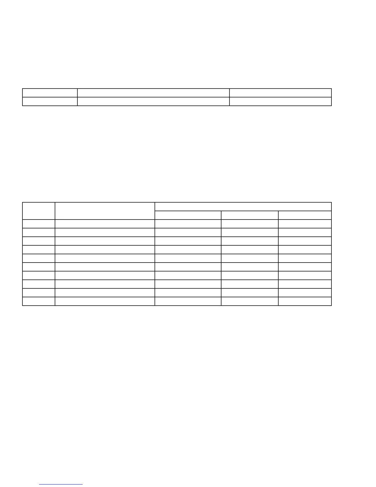
Table F: Available Component Tests
Test # Component Description
Available Status Indicators
OK O/Open On/Shorted
0 Temp Sensor A - Evaporator 0- 00 01
1 Temp Sensor B - Display 1- 10 11
2 Compressor n/a 20 21
3 Interior/Ice Maker Fan n/a 30 31
4 Reverse Gas Solenoid n/a 40 41
5 Condenser Fan n/a 50 51
6 Mullion Heater n/a 60 61
7 Door A Sense n/a 70 71
8 Door B Sense n/a 80 81
9 Door C Sense n/a 90 91
Note: Must use magnet to change state of Door C Sense
Disabling Service Mode:
To exit service mode, press and hold the “WARMER” button while pressing the ”COLDER” button four times within ve seconds.
Service Mode will automatically disable after ve minutes of no keypad entry.•
USER INTERFACE PANEL AND CONTROL SYSTEM
REFRIGERATION MONITOR