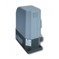
M A C
8
Once you have defined and satisfied these requirements, proceed with the assembly:
•Fixtherearjunctiontothepillarbuwelding(Fig.5) ;
•Fixthefrontjunctiontothegatebywelding(Fig.6) ;
•Keeping the motor in a horizontal position, mount it first to the front bracket, then to the rear bracket (Fig. 7) ensuring that installa-
tion dimensions shown in Figure 4 are respected .
WARNING In order to make the structure sufficiently strong, reinforcement plates to be fixed to attachments may be necessary.
WARNING Grease pins before assembly.
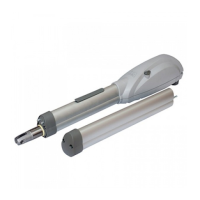
How to unlock the operator:
•TurnthecapplacedonthebackofMACinordertodiscovertheunderlyingshapedhole ;
•Insertthereleasekeyinsidetheshapedholepayingattentiontothedirectionofinsertion(Fig.8.a) ;
•Rotate90degrees(counterclockwisetounlock,clockwisetolock)thereleasekey(Fig.8.b) .
WARNING Remember to protect the lock with the respective cover so that the operator is protected by water or powder (even
when it remains unlocked for a long time).
WARNING During this operation gate may perform uncontrolled movements: operate with extra care so to avoid any risk.
5 ELECTRICAL CONNECTIONS
WARNING DEA System reminds you to execute any wiring or maintenance operation with power supply disconnected.
WARNING To ensure an appropriate level of electrical safety always keep the 230V power supply cables apart (minimum 4mm
in the open or 1 mm through insulation) from low voltage cables (motors power supply, controls, electric locks, aerial and auxiliary
circuits power supply), and fasten the latter with appropriate clamps near the terminal boards.
WARNING During the connection phase, fasten the electric cables with appropriate clamps near the terminal boards and, when
possible, unsheathe the cables to avoid they are too long.
MAC must be electrically connected to a DEA System control panel; refer to the instructions provided for such device for further
information.
For MAC wiring, proceed as follows:
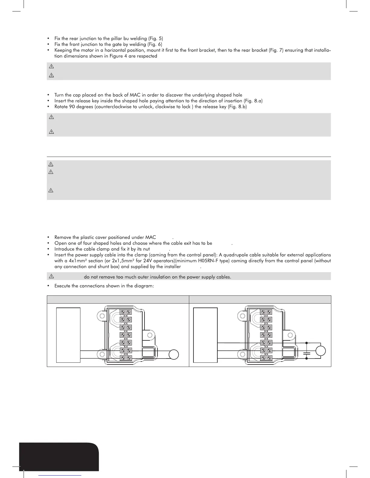
Connection for 24V and 230V
•RemovetheplasticcoverpositionedunderMAC (Fig. 9).
•Openoneoffourshapedholesandchoosewherethecableexithastobe (Fig. 10).
•Introducethecableclampandfixitbyitsnut (Fig. 11).
•Insert the power supply cable into the clamp (coming from the control panel): A quadrupole cable suitable for external applications
with a 4x1mm² section (or 2x1,5mm² for 24V operators)(minimum H05RN-F type) coming directly from the control panel (without
any connection and shunt box) and supplied by the installer (Fig. 12).
WARNING do not remove too much outer insulation on the power supply cables.
•Executetheconnectionsshowninthediagram:
24V 230V
CHIUDE
APRE
M
CENTRALE DI COMANDO
ELECTRONIC BOARD
ARMOIRE DE COMMANDE
CUADRO DE MANIOBRAS
CENTRAL DE COMANDO
1(rosso)
2(blu)
CHIUDE
COMUNE
APRE
M
CENTRALE DI COMANDO
ELECTRONIC BOARD
ARMOIRE DE COMMANDE
CUADRO DE MANIOBRAS
CENTRAL DE COMANDO
1(bianco)
2(blu)
3(nero)