H – Electric Connection
INM.XX.X.00 H-3 April, 2018
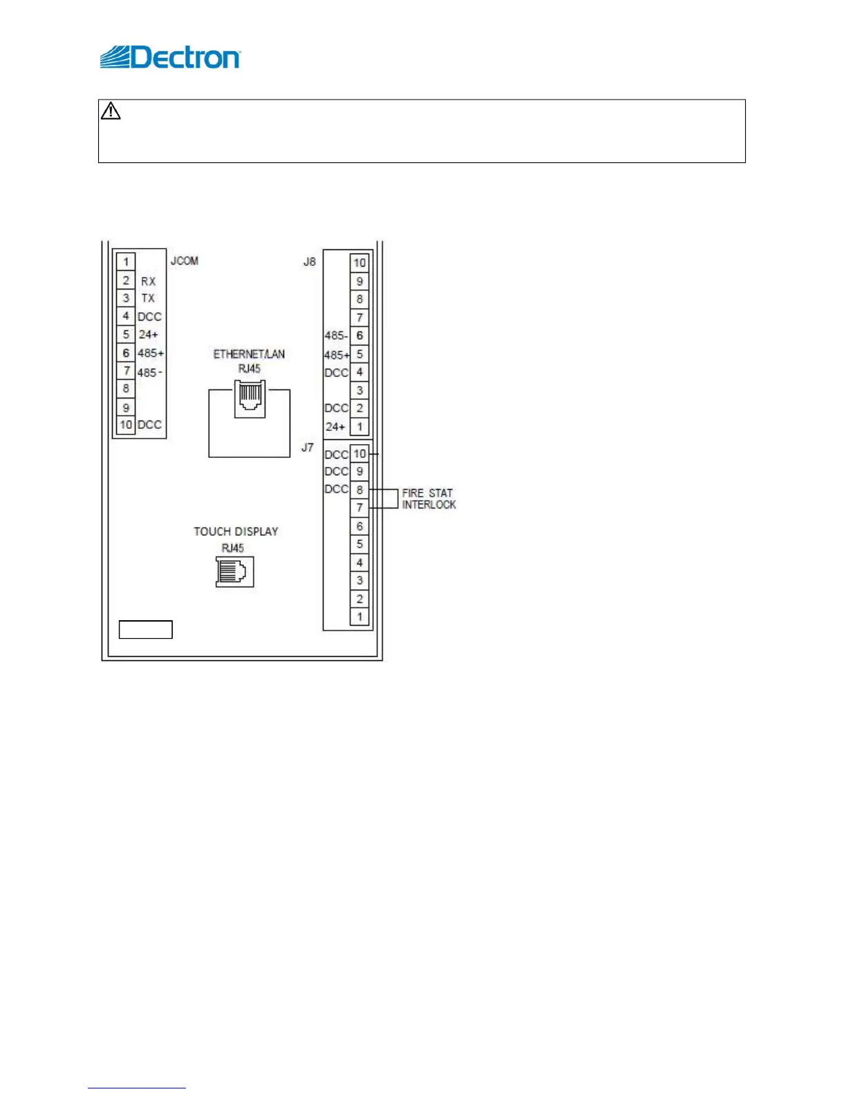
Some of the most common systems/devices, connected to dehumidifier, are various BMS (Building Management
System), local safety systems (fire and smoke detection) and dehumididfier remote operator panel (ROP). Pic. H.3
below shows dehumidifier control board terminals used for said control wiring.
For other control connections refer to
dehumidifier submittal documentation and
wiring diagrams; contact the factory as needed.
Fire/Smoke detecting system interlock.
Dehumidifier control system can be interlocked
with external fire/smoke alarm system (to stop
dehumidifier operation if fire or smoke is
detected). Control board accepts dry-contact
signal (closed contact is accepted as NO FAULT;
open contact is accepted as FAULT/ALARM).
To do so, remove the factory installed
jumper from pins 8 and 7 on board terminal J7
(see Pic. H.3) and connect dry-contact signal
wires there.
Operator Panel local and remote installation.
Touch Display operator panel (OP) is provided
with the dehumidifier (to allow for operator –
maintenance, service personnel etc. –
communication to the equipment).
Touch Display OP communicates over RS-485
serial port; panel is equipped with RJ-45 socket.
Touch Display OP is normally installed inside the dehumidifier (referred to as local operator panel), and normally
connected with factory-provided “patch” (straight-through) cable, plugged into dedicated control board RJ-45
socket (see Pic. H.3); this RJ-45 socket is internally connected to same serial port as pins 6 (485+) and 7 (485-) on
the board terminal JCOM.
NOTE: It is not recommended to have multiple devices (Ops, etc.) connected to the same serial port; do not
connect any other device (ROP etc.) to pins 6 and 7 on terminal JCOM, if local OP is plugged into RJ-45.
Same or similar (additional) panel could be installed remotely, as far as 1000’ away from the dehumidifier (remote
operator panel – ROP). ROP Touch Display is normally connected to pins on the terminal J8:
Use a CAT5 or CAT6 cable. If the cable comes with RJ-45 jacks on both ends – cut one end off; if no jacks
attached, attach it one side of the cable, using respective T568 wiring standard (A or B, see Pic. H.4).
Connect cable to control board pins on terminal J8 – see table H.1 below (terminal JCOM pins layout is
referenced also, in case of direct wiring (bypassing dedicated RJ-45 jack) is needed).
o Multiple devices could be connected to same 24VDC power and common board pins, load permitting.
CAUTION! Dehumidifier control board is designed to operate with 24VAC and 24VDC circuitry only!
Connecting higher voltage circuitry to the dehumidifier control board can cause failure or malfunction of the
board and/or other connected devices!
Pic.H.3