G – Piping Connection
INM.XX.X.00 G-1 April, 2018
Piping Connection
Piping Connection General Considerations
Refer to the equipment main label and stickers at lines/piping termination to verify respective connecting
lines’ sizes, flow directions (IN/OUT) and system type (pool heating, space heating, etc.).
o Flow direction stickers at respective piping stubs refer to the equipment it’s attached to: IN – media
(water, refrigerant, etc.) entering the equipment, OUT – leaving the equipment.
o Select the line/piping size based on the equipment documentation (labels, drawings, etc.): diameters
of the dehumidifier or OACC/OAFC piping stubs may be different from the required line size.
Use proper materials and pipe joining methods, respective to given system (system media, pressure, etc.).
Use proper installation field practices and Code(s) requirements (proper piping support, no pipe-to-edge
contact, grounding/bonding, insulation, pressure testing, charging/filling, etc.)
As/where needed, ensure that proper isolation and balancing means (valves, circuit setters, etc.) are in place.
For water or water/glycol systems (pool water, space heating or cooling water, etc.) - provide proper means
for priming (filling), draining and aerating (bleeding the air from the system): install automatic air bleeding
valve(s) at each local top point of the system and drain/priming valves at the lowest point(s) of the system.
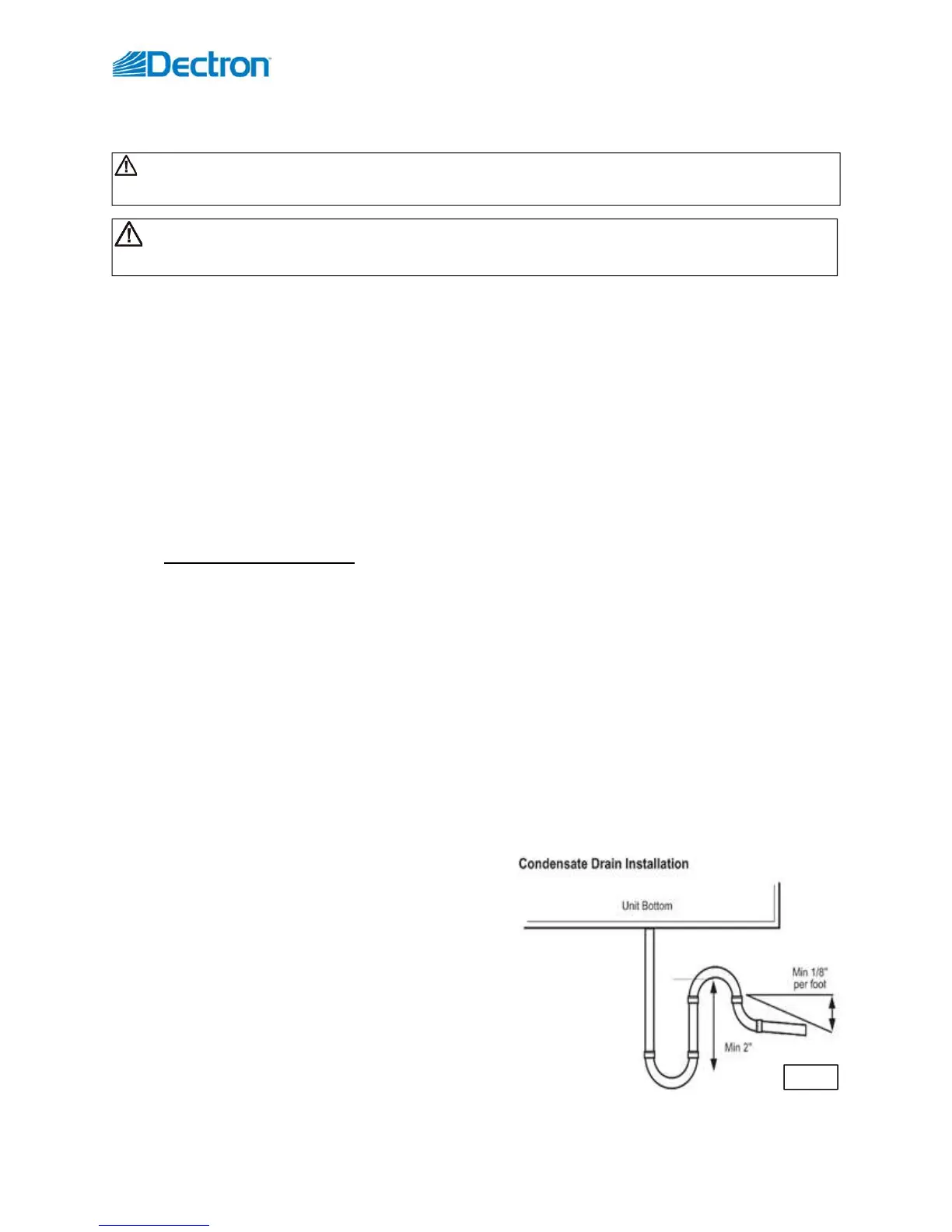
Condensate Drain Connection and P-trap Installation
Each dehumidifier drain pan condensate line must be directed to an external drain and equipped with a P-trap to
ensure proper drainage.
o If gravity disposal of condensate is not possible, use a condensate pump.
o If the drain line passes through an unconditioned/not-heated space, heat tracing is required to prevent the
condensate in the drain from freezing.
Dehumidifier condensate termination(s) (or it’s location) is normally marked with respective label, stating whether
given line is already equipped with a P-trap from the factory or not. If not, install a P-trap
P-trap installation:
o Make sure that each drain connection has a P-trap
o Make sure that there is only one P-trap installed (do not
double-trap).
o If soft piping material is used (braided hose, etc.)
- ensure the drain line is not sagging (this may
create “double-trapping effect” and prevent
condensate from proper drainage).
o Pitch the condensate drain line minimum of 1/8” per
linear foot and support the pipe with code-approved
hangers at least every 5 feet (see Pic. G.1).
CAUTION! When connecting the equipment to external mechanical and electrical systems, refer to
submittal documentation and equipment labels and stickers for piping connection details.
Pic.G.1
WARNING! All work must be done by qualified personnel in accordance with local and national Codes,
Standards and Regulations as well as respective design/submittal documentation and Dectron recommendations.