G – Piping Connection
April, 2018 G-2 INM.XX.X.00
Pool Water Heating Piping
Pool Water Piping Connections – General Considerations
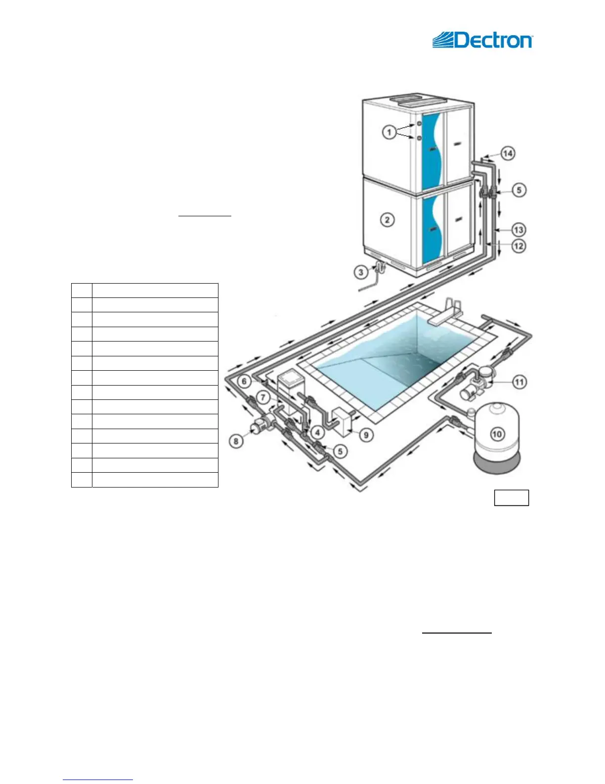
As shown on Pic. G.2, the chemical feeder must be located downstream of (after) the dehumidifier to prevent
the pool water heat exchanger from being exposed to high chemical concentration.
Auxilliary pump or main pool pump must be located upstream of (before) the dehumidifier.
o The dehumidifier normally requires constant waterflow through (to ensure proper automatic control
over pool heating feature); however, if requested, it could be equipped with means to control
auxiliary pump. This set up would also require a pool water temperature sensor to be installed in the
external pool water manifold/piping. Contact the factory if needed.
Proper waterflow direction (refer to the dehumidifier piping termination stickers – Pool IN/Pool OUT), rate,
GPM, and line set size (refer to dehumidifier Main Lable) must be maintained for proper and troublefree
operation.
o It is recommended to have means to adjust/balance waterflow (circuit setters, etc.)
o Some dehumidifiers can be equipped with “full flow” heat exchangers (allowing for full volume of
pool water flow) – refer to the main label info (pool water GPM).
1 OACC/OAFC connections
2 Dehumidifier
3 P-Trap/condensate line
4 Check Valve
5 Ball valve(s)
6 Flow Meter
7 Auxiliary Pool Heater
8 Aux. Pump (lowest point)
9 Automatic Chemical Feeder
10 Pool Filter
11 Main Pool Pump
12 Pool Water Inlet (IN)
13 Pool Water Outlet (OUT)
14 Air Vent
If the dehumidifier is equipped with a pool water heater (to
utilize compressor-generated heat for pool water heating), it
would require pool water piping connected to respective
dehumidifier pipe terminations.
Pic. G.2 shows an example of a generic pool water piping
schematic.
NOTE: this schematic is an example only - design, provision and
installation of actual pool water piping is not Dectron’s
responsibility and is to be done by a third party.
Pic.G.2
 Loading...