EasyManuals Logo

Definox DCX3 User Manual

Definox DCX3
55 pages
To Next Page IconTo Next Page
To Previous Page IconTo Previous Page
Page #10 background imageLoading...
Page #10 background image
MAINTENANCE NOTICE
NM-230 index 18
Page 10/55 September 2020
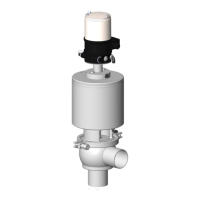
4.4
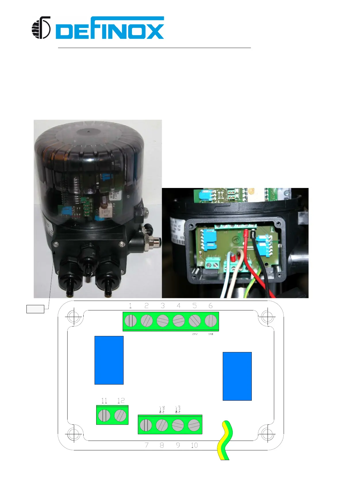
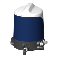
CONNECTING THE POWER SUPPLY REGULATOR OPERATION
The signal from a temperature sensor or level, flow, which through with the control box of
the valve that controls it (Regulator mode).
Remove the 4 screws from the electrical connection box using a flat screwdriver.
Connect the 24VDC+ wire (red) to 24V [5]
Connect the 24VDC- wire (black) to GND [6]
Connect the 4-20mA+ wire (blue) to bin-/Proz1 [8]
Connect the 4-20mA- wire (white) to bin2+/Proz2 [9]
Screw

Table of Contents

Other manuals for Definox DCX3

Questions and Answers:

Question and Answer IconNeed help?

Do you have a question about the Definox DCX3 and is the answer not in the manual?

Definox DCX3 Specifications

General IconGeneral
BrandDefinox
ModelDCX3
CategoryControl Unit
LanguageEnglish

Related product manuals