EasyManuals Logo

Deif GPC-3 Quick Start Guide

Deif GPC-3
23 pages
To Next Page IconTo Next Page
To Previous Page IconTo Previous Page
Page #10 background imageLoading...
Page #10 background image
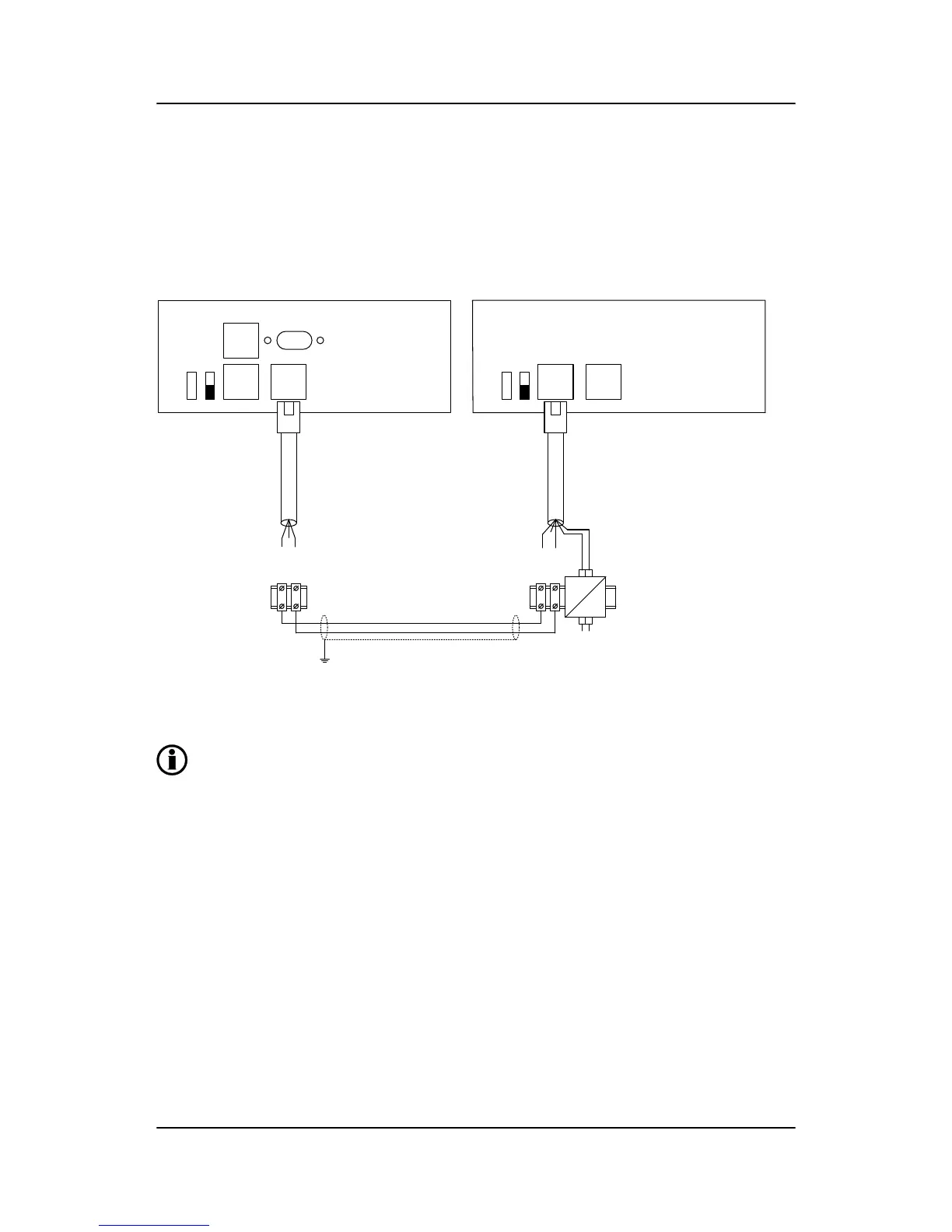
3.1.4 Connecting the additional operator panel, AOP-2 (optional)
The CAN cable for the CAN bus communication between the display unit of main unit no. 1 and the AOP-2
has to be connected to the CAN port (CAN 2) of the display unit (DU-2) and the CAN port (CAN 1) of the
AOP-2 as shown in the drawing below.
Standard display DU-2
OFF
ON
App./Bootl.
End Res.
CAN 1
AOP-1
CAN 2
ML - 2
Green
Blue
DIN Rail
Additional Operator Panel AOP-2
OFF
ON
App./Bootl.
End Res.
CAN 1 CAN 2
Green
Blue
DIN Rail
5V DC
24V DC
+
-
+
-
White
Black
1
2
1
2
Twisted pair max. 200m
Cable shield
The AOP-2 can be placed up to 200 m from the main display. The AOP-2 requires a separate power supply
unit, while the display receives the power supply through the display cable from the main unit.
For further information about the installation of multiple displays and AOP-2s, please refer to
the document "Description of Option X".
ML-2 quick start guide 4189340603 UK Getting started
DEIF A/S Page 10 of 23

Other manuals for Deif GPC-3

Questions and Answers:

Question and Answer IconNeed help?

Do you have a question about the Deif GPC-3 and is the answer not in the manual?

Deif GPC-3 Specifications

General IconGeneral
BrandDeif
ModelGPC-3
CategoryController
LanguageEnglish

Related product manuals