5. Configuring the speed governor and AVR out-
puts
5.1 Settings for speed governor and AVR control
Dependent on the hardware configuration, relays or analogue outputs can be used for speed governor and
AVR control.
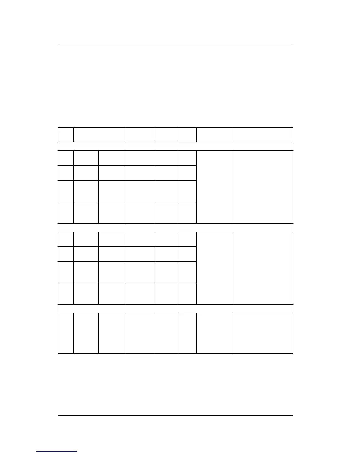
The settings used for this are the following:
No. Setting Min.
Max.
Factory
setting
Notes Ref. Description
2600 Relay control
2601 Relay
control
GOV ON
time
10 ms
6500 ms
500 ms Designer’s
Reference
Handbook
GPU:
Option G2
This menu is only availa-
ble if "Relay" is selected
in menu 2781.
Normally used: Relay 65
for increase and relay 67
for decrease.
2602 Relay
control
GOV peri-
od time
50 ms
32500 ms
2500
ms
2603 Relay
control
Increase
relay
Not used
Option-
dep.
Relay
65
2604 Relay
control
Decrease
relay
Not used
Option-
dep.
Relay
67
2720 Relay control (AVR)
2721 Relay
control
AVR ON
time
10 ms
3000 ms
100 ms Option:
AVR control
(D1)
Relay outputs for voltage/
var/power factor control.
This menu is only availa-
ble if "Relay" is selected
in menu 2782.
Normally used: Relay 69
for increase and relay 71
for decrease
2722 Relay
control
AVR per
time
50 ms
1500 ms
500 ms
2723 Relay
control
U in-
crease
Not used
Option-
dep.
Relay
69
2724 Relay
control
U de-
crease
Not used
Option-
dep.
Relay
71
2780 Regulator output
2781 Reg.
output
GOV Relay
EIC
Relay Designer’s
Reference
Handbook
GPU:
Option G2
Selection of the speed
output: Relay, analogue
or engine interface com-
munication. Analogue
and EIC are option-de-
pendent.
ML-2 quick start guide 4189340603 UK Configuring the speed governor and AVR
outputs
DEIF A/S Page 22 of 23

 Loading...


