tor. If the genset is running in parallel, the active or reactive nominal power setpoint value will be changed. If it
is a stand-alone genset not parallel to the mains, the nominal frequency or voltage setpoint will be changed
and also displayed. When the "back" button is activated, the regulation setpoint returns to nominal.
If the digital inputs or AOP buttons are activated in semi-auto, the regulation window is auto-
matically opened.
8.2.9 Auto and test mode (AGC 200/AGC-3/AGC-4 only)
Similar to semi-auto except from the fact that activating the digital inputs or AOP buttons for governor or AVR
control will change the regulation setpoint but not open the regulation window. When the digital inputs or AOP
buttons are deactivated, the regulation setpoint returns to nominal.
PPM: Test mode is only available for an emergency generator.
AVR setpoint manipulation requires option D1.
Regarding AOP setup, please refer to "Help" in the PC utility software.
8.3 Relay output adjustments
8.3.1 Relay output adjustments
If the relay outputs are used for the speed governor/AVR, it will be necessary to adjust the relay minimum
pulse time and the period time.
There are two settings: ON time, which is the shortest relay ON signal time.
PER time, which is the period time.
The shortest acceptable pulse time is depending on the reaction of the governor/AVR and connection type.
Slow reaction requires a long time pulse.
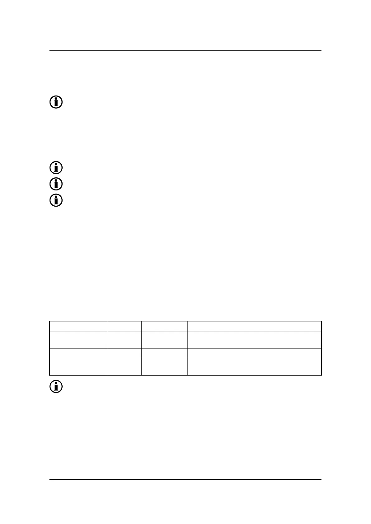
As a starting point, use the following settings for the relay ON time and relay period time:
Governor ON time Menu 2601 500…1000 ms
Governor period time Menu 2602 2500…5000 ms It is recommended that the period time is approxi-
mately 5xON time.
AVR ON time Menu 2721 100 ms
AVR period time Menu 2722 500 ms It is recommended that the period time is approxi-
mately 5xON time.
It is still necessary to tune in the P controllers.
8.4 Resulting speed/voltage curve upon load change
8.4.1 Resulting speed/voltage curve upon load change
Testing is easily done by using (if possible) a load bank applying "jumps" in the generator load, hereby testing
the speed/voltage control.
General guidelines for commissioning
4189340703 UK
Adjustment
DEIF A/S Page 23 of 25