8. Adjustment
8.1 Adjustment overview
8.1.1 Overview
The adjustment of the unit can be carried out when the initial settings of the governor and the AVR are made.
The controller of the unit is a PID controller.
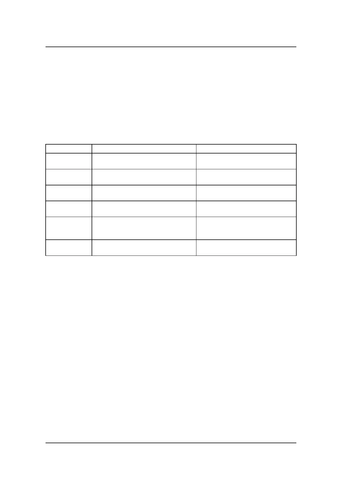
The unit includes different controllers which must be tuned in at the correct running situations (see the table
below):
Controller Purpose Tune in conditions
Frequency con-
troller
Controls the frequency when the Multi-line
2 is in island mode (stand-alone).
Tune in when the generator is running
with the generator breaker open.
Power controller Controls the power when the Multi-line 2 is
running with fixed power/base load.
Tune in when the generator is running
parallel to the mains.
P load share con-
troller
Controls the power when the Multi-line 2 is
running in load sharing mode.
Tune in when the generator is running in
load sharing mode.
Voltage controller Controls the voltage when the Multi-line 2
is in island mode (stand-alone).
Tune in when the generator is running
with the generator breaker open.
Reactive power
controller
Controls the VAr when the Multi-line 2 is
running with fixed VAr load.
Tune in when the generator is running
parallel to the mains or in load sharing
mode.
Q load share
controller
Controls the reactive power when the Mul-
ti-line 2 is running in load sharing mode.
Tune in when the generator is running in
reactive load sharing mode.
8.2 Adjusting PID controller
8.2.1 PID controller
Before the PID controllers of the Multi-line 2 are tuned in, the values of the K
p
, Ti and Td of all controllers
must be decreased to a low value.
Start by tuning in the K
p
factor, and then tune in the Td and Ti. Normally, the controllers are tuned in following
a few general rules as given below.
8.2.2 Step 1, adjustment of the KP
Only the P regulator is to be active (Td and Ti set to 0 s), and the operation of the genset must be stable. Now
increase the K
p
factor step by step, until the genset becomes unstable. Adjust the K
p
factor to 50% of the
value found above.
8.2.3 Step 2, adjustment of the Ti
With the K
p
setting set to the value found in step 1, raise the Ti to a high value, e.g. 30 s, and decrease Ti
step by step, until the genset becomes unstable. Adjust the Ti to approx. 1.5-1.7 times the value where insta-
bility begins.
8.2.4 Step 3, adjustment of the Td
Step by step increase the Td until the genset becomes unstable. Adjust the Td to 50…70% of the value.
General guidelines for commissioning
4189340703 UK
Adjustment
DEIF A/S Page 21 of 25