2.2.3 Parameter setup regulator governor
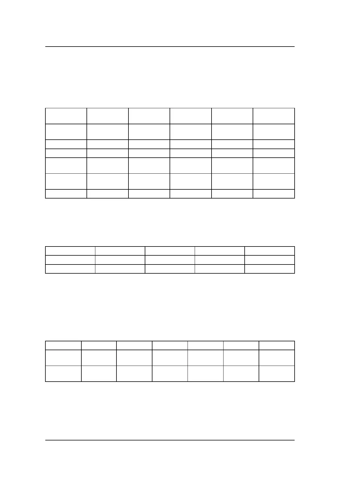
The table below illustrates the differences in the regulator parameter setup. In PPU-3, the possibility to adjust
the differential band in the regulator has been added.
Parameter setup regulator governor
Parameter
PPU-2
Description Address Parameter
PPU-3
Description Address
2122 Freq. control
Kp
92 2511 f Kp 122
2123 Freq. control Ki 93 2512 f Ti 123
2513 f Td 124
2132 Power control
Kp
15 2531 P Kp 126
2133 Power control
Ki
50 2532 P Ti 127
2533 P Td 128
2.2.4 Parameter setup relay or analogue governor
In PPU-3, it is possible to change between relay and analogue governor setup, see the table below.
Parameter setup relay or analogue governor
Controller Parameter Description Address Set point
PPU-2 N/A N/A N/A N/A
PPU-3 2781 Reg. output GOV 183 Relay or analogue
2.2.5 Parameter setup governor relay
The PPU-2 standard unit controls the governor on relay output terminals 65-68, slot #4, these are not configu-
rable. The PPU-3 standard unit has four configurable relay outputs, placed in slot #4, terminals 65-72. The
table below shows the differences in the standard parameter settings.
Parameter setup governor relay
Controller Parameter Description Address Value Output A Output B
PPU-2 2252 GOV period
time
122 ms N/A N/A
PPU-3 2602 GOV period
time
144 ms Terminal 65 Terminal 67
ML-2 application notes Converting PPU-2
to PPU-3 4189341126 UK
Application and installation
DEIF A/S Page 14 of 18
 Loading...


