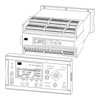
PPM Installation Instructions
DEIF A/S Page 14 of 69
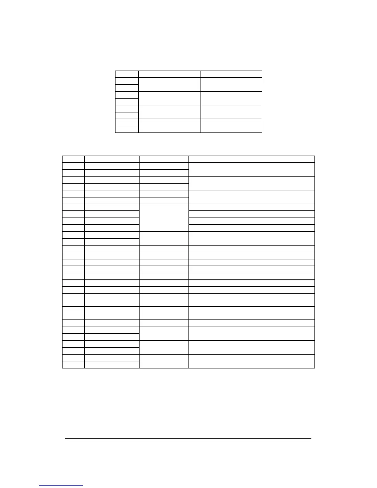
Option M18
4 x relay outputs.
Term. Function Description
90 Relay output 14
250V AC, 8A max.
Configurable
91
92 Relay output 15
250V AC, 8A max.
Configurable
93
94 Relay output 16
250V AC, 8A max.
Configurable
95
96 Relay output 17
250V AC, 8A max.
Configurable
97
Slot #7, engine interface board
Term. Function Technical data Description/preconfiguration
98 Analogue input 1 + +4…20 mA in Heavy consumer 1 variable load/configurable
99 Analogue input 1 - GND
100 Analogue input 2 + +4…20 mA in Heavy consumer 2 variable load/configurable
101 Analogue input 2 - GND
102 Analogue input 3 + +4…20 mA in Configurable. User-programmable
103 Analogue input 3 - GND
104 Binary input With wire break
supervision
Wire break
resistor: 100
Configurable. User-programmable
105 Binary input Configurable. User-programmable
106 Binary input Configurable. User-programmable
107 Common Common terminals for 104-106
108 Tacho input 0.5…70V AC
10…10.000 Hz
RPM/magnetic pick-up/overspeed
109 Tacho input
110 Binary input Optocoupler Configurable/Semi-auto mode
111 Binary input Optocoupler Configurable/Auto mode
112 Binary input Optocoupler Configurable/Split mode
113 Binary input Optocoupler Configurable/Shaft (or Shore) mode
114 Binary input Optocoupler External emergency stop activated
115 Binary input Optocoupler Ready for operation (ON = ready, OFF = blocked)
116 Binary input Optocoupler Running feedback
117 Binary input Optocoupler Remote start (only active in SEMI-AUTO plant
mode)
118 Binary input Optocoupler Remote stop (only active in SEMI-AUTO plant
mode)
119 Com. Common Common for terminals 114-118
120 NO Relay 18
250V AC/8A
Start
121 Com.
122 NO Relay 19
250V AC/8A
Stop coil/running coil (selectable)
123 Com.
124 NO Relay 20
250V AC/8A
Start prepare
125 Com.