PPM Installation Instructions
DEIF A/S Page 5 of 69
3. General hardware description
Hardware
The unit housing is divided into board slot positions. This means that the unit consists of a
number of printed circuit boards (PCBs) mounted in numbered slots. The green terminal blocks
are then mounted in the PCBs. Some of these board slots are standard, and some are intended
for options. The board slot positions are arranged as illustrated below.
Term. DG SG/SC TB Description
Slot #1 1-28 Standard Standard Standard Power supply board
Slot #2 29-36 H2 H2 H2 Option: External comm.
Slot #3 37-64 Standard Standard Standard Load sharing and
input/output board
Slot #4 65-72 Standard
Not used Not used
Outputs for governor/AVR
according to choice of types
Slot #5 73-89 Standard Standard Standard AC measuring
Slot #6 90-125 F1,
M15, M16,
M18
F1,
M15, M16,
M18
F1,
M15, M16,
M18
Option: F1 analogue
transducer outputs,
M15 (4 x 0(4)…20 mA inputs),
M16 (7 x binary inputs),
M18 (4 x relay outputs)
Slot #7 98-125 Standard Standard
Not used
Engine interface board
Slot #8 126-133 Standard Standard Standard Internal CANbus
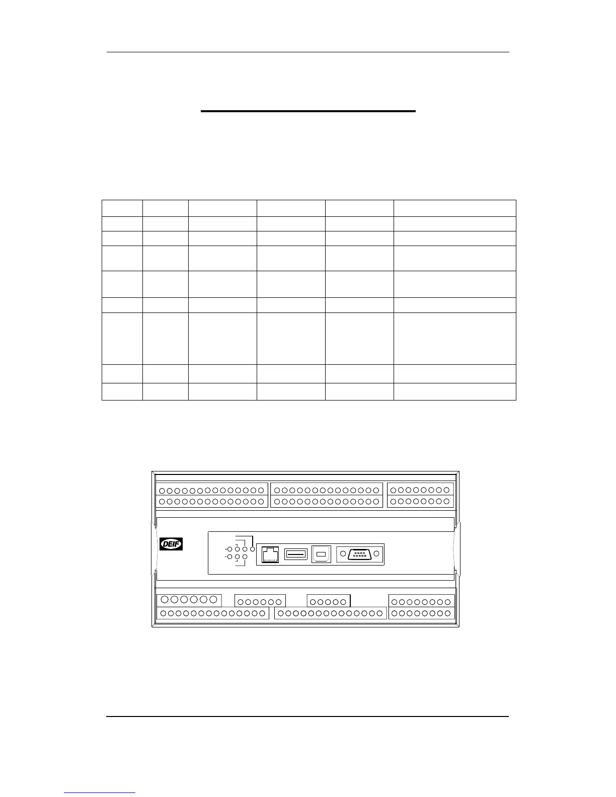
Unit top side overview
An overview of the terminals is presented below. The slot positions are as follows:
Ethernet
787776757473
96 979594929190 93
89888785 8683 8482818079
727169 70686765 66
62 6359 60 615856 575553 54 645251504947464443 45 4841403837 39 42
USB Memory Service port Display
Ethernet
PMS CAN
Engine CAN
USB
Power
Self check ok
Alarm inhibit
SLOT # 1
SLOT # 3
SLOT # 5
SLOT # 7
SLOT # 2
SLOT # 4
SLOT # 6
SLOT # 8